Transistor hFE Test
Diode Test
• Overload protection: 250V effective value.
• ForwardDCcurrent:approximate1mA.
• ReversedDCvoltage:approximate3.0V.
Continuity
• Overloadprotection:250Veffectivevalue.
Opencircuitvoltage:approximate3.0V.
Capacitor
• Overload protection: 250V effective value.
Battery
PRIOR TO USE
Thoroughlyreadandunderstandtheoperatinginstructions.
• Check9vbattery,ifthebatteryvoltageislessthan7v,display
willshow'',thebatteryshouldbereplacedatthistimeto
ensuremeasuringprecision.
• Payattentiontothe""besidestheinputjackwhichshows
thattheinputvoltageorcurrentshouldbewithinthespecified
value.
• Therangeswitchshouldbepositionedtothedesired
measurementrangeformeasurementbeforeoperation.
OPERATING INSTRUCTIONS
Measuring DC Voltage
• ConnecttheblacktesttoCOMjackandtheredtoVΩmAjack.
• SettherotaryswitchatthedesiredVrangeposition.
• Connecttestleadsacrossthesourceorloadunder
measurement.
• YoucangetreadingfromLCD.Thepolarityoftheredlead
connectionwillbeindicatedalongwiththevoltagevalue.
Note:
• Whenthevaluescaletobemeasuredisunknownbeforehand,
settherangeselectoratthehighestposition.
• Whenthefigure'1'of'-1'isdisplayed,itindicatesover-
rangesituationandthehigherrangehastobeselected.
• ""meansyoucan'tinputvoltagehigherthan600V,it's
possibletoshowhighervoltage,butitmaydestroytheinner
circuitorposeashockhazard.
• Alwaysexercisecautionwhenworkingwithelectric,ifinany
doubtseekadvicefromaqualifiedelectrician.
Measuring AC Voltage
• ConnecttheblacktesttoCOMjackandtheredtoVΩmAjack.
• SettherotaryswitchatthedesiredV~rangeposition.
• Connecttestleadsacrossthesourceorloadunder
measurement.
Note:
• Whenthevaluescaletobemeasuredisunknown,setthe
rangeselectoratthehighestposition.
• Whenonlythefigure'1'or'-1'isdisplayed,itindicatesan
over-rangesituationahigherrangeshouldbeselected.
• ""meansyoucan'tinputvoltagehigherthan600V,it's
possibletoshowhighervoltage,butitmaydestroytheinner
circuitorposeashockhazard.
• Alwaysexercisecautionwhenworkingwithelectric,ifinany
doubtseekadvicefromaqualifiedelectrician.
Measuring DC/AC Current
• ConnecttheblacktestleadtoCOMjackandtheredtothe
VΩmAjackforamaximum200mAcurrent.
• SettherotaryswitchatthedesiredA/A~rangeposition.
• Connecttestleadsinserieswiththeloadundermeasurement.
• Thepolarityoftheredleadconnectionwillbeindicatedalong
withthecurrentvalue.
Note:
• Whenthevaluescaletobemeasuredisunknown,setthe
rangeselectoratthehighestposition.
• Whenonlythefigure'1'or'-1'isdisplayed,itindicatesan
over-rangesituationahigherrangeshouldbeselected.
• ""meansthesocketmA'smaximumcurrentis200mAand
10A'smaximumcurrentis10A,overcurrentwilldestroythe
fuse.Since10Aisnotfused,themeasuringtimeshouldbe
lessthan1secondtopreventprecisionfromaffectingbycircuit
heating.
Measuring Resistance
• ConnecttheblacktestleadtoCOMjackandtheredtoVΩmA
jack.
• SettherotaryswitchatthedesiredΩrangeposition.
• Connecttestleadsacrosstheresistanceundermeasurement.
• YoucangetreadingfromLCD.
Note:
• Whenonlythefigure'1'or'-1'isdisplayed,itindicatesan
over-rangesituationahigherrangeshouldbeselected.
• Formeasuringresistanceabove1MΩ,themetermaytakea
fewsecondstogetastablereading.
• Whentheinputisnotconnected,i.e.atopencircuit,thefigure
'1'willbedisplayedfortheover-rangecondition.
• When checking in-circuit resistance, be sure the circuit
under test has all power removed and that all capacitors
have been discharged fully.
• Whenthevaluescaletobemeasuredisunknown,setthe
rangeselectoratthehighestposition.
Transistor Testing
• Settherotaryswitchat'hFE'position.
• DeterminewhetherthetransistorundertestingisNPNorPNP
andlocatetheemitter,baseandcollectorleads.Insertthe
leadsintoproperholesofhFEsocketonthefrontpanel.
• ReadtheapproximatehFEvalueatthetestingconditionof
basecurrent1b10uAandVce3V.
Diode Testing
• ConnecttheblacktestleadtoCOMjackandtheredtoVΩmA,
jack.(Thepolarityofredlead'+').
• SettherotaryswitchattheFrangeposition.
SAFETY INSTRUCTIONS
Itisimportanttoreadandunderstandyourinstructionmanual.
Learnthetoolsapplication,aswellasit'slimitationsandthe
potentialhazardsassociatedwiththistool.
ADDITIONAL SAFETY INFORMATION FOR MULTIMETER
• ThemeterisdesignedaccordingtoIEC-1010withan
over-voltagecategory(CATIII)andpollution2.
• Followallsafetyandoperatinginstructionstoensurethat
themeterisusedsafelyandiskeptingoodoperating
condition.
• SafetySymbols:
Importantsafetyinformation,refertotheoperatingmanual.
Dangerousvoltagemaybepresent.
• Doubleinsulation(ProtectionClassIII).
• Themeterissafeonlyaccordingtostandardprocedures
whenusedinconjunctionwiththesuppliedtestleads.Replace
damagedtestleadsonlywiththesamemodelorsame
electricspecifications.
• Donotusethemeterbeforethecoverisinplacetoavoid
riskofelectricshock.
• Therangeswitchshouldbeintherightpositionfortesting.
• Toavoidelectricshockanddamagingtheinstrument,theinput
signalsshouldnotexceedthespecifiedlimits.
• WhenmeasuringswitchedpowersuchasTVsets,attention
shouldbepaidtothepossiblepulsesthatmaycause
destructionofthecircuit.
• Rangeswitchpositionshouldneverbechangedatrandom
duringmeasurement.
• Cautionagainstshockwhenmeasuringvoltageshigherthan
DC60V&AC30V.
• Protectionfuseshouldbereplacedonlywithsametypeand
specification.
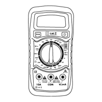
1.LCDDisplay:3
1
/2digits,character16mmhigh
2.BackLightButtonSwitch:Pressbuttontoswitchonthe
backlight,itwillautomaticallyswitchoffafter5seconds.
3.Rotaryswitch:usethisswitchtoselectfunctionsandranges.
4.VΩmACx+InputJack
5.COMInputJack
6.Cx-InputJack
7.Data-holdSwitch(HOLD)
SPECIFICATIONS
• Maxvoltagebetweeninputterminalandearthground:CAT
III600V.
• Over-rangeindication:display"1"forthesignificantdigit.
• Automaticdisplayifnegativepolarity"_".
• Lowbatteryindication:''displayed.
• MaxLCDdisplay:1999(3
1
/2)digits).
• Fuseprotection:F-200mA/250V(ø5x20mm).
• Powersupply:9Vbattery.
• Operatingtemp:0˚C(relativehumidity<85%).
• Storagetemp:10˚Cto50˚C(relativehumidity<85%).
• Guaranteedprecisiontemp:23+5˚C(relativehumidity<85%).
• Dimensions:143x75x32mm.
• Weight:approx200g(includingbattery).
Accuracyisspecifiedforaperiodof1yearaftercalibrationandat
18˚Cto28˚C(64˚Fto82˚F)withrelativehumidityto75%.
DC Voltage
• Inputimpedance:10MΩ.
• Overloadprotection:250Vfor200mVrange,effectiveDCor
AC600Vforotherranges.
AC Voltage
• Frequencyrange:40to400HZ.
• Response:average,calibratedinrmsofsinewave.
DC Current
• Overloadprotection:F200mA/250Vfuse.
AC Current
Resistance
• Overload protection: 250V effective value.
1
5
3
2
4
6
7
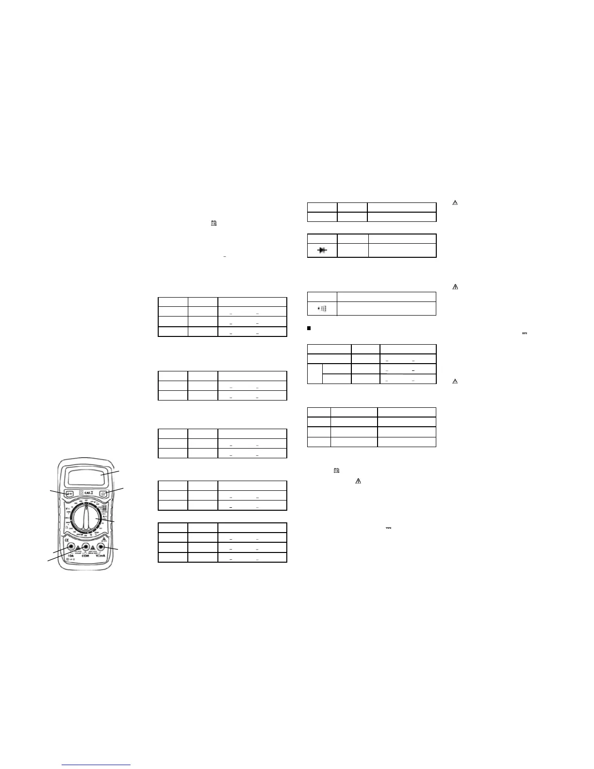
Product Familiarisation
Digital Multimeter
Range
Resolution Accuracy
200V
100mV +1.2%ofrdg+20digits
600V
1V
+1.2%ofrdg+20digits
Range
Resolution Accuracy
200uA
0.1µA +1.0%ofrdg+20digits
200mA
0.1mA
+1.5%ofrdg+20digits
Range
Resolution Accuracy
200uA
0.1µA +1.8%ofrdg+20digits
200mA
0.1mA
+2.5%ofrdg+20digits
Range
Resolution Accuracy
200Ω
0.1Ω +1.0%ofrdg+25digits
20KΩ
10Ω
20MΩ
10KΩ
+1.0%ofrdg+20digits
+2.5%ofrdg+20digits
Range
TestRange TestCurrent/Voltage
NPN&PNP
0-1000 Ib=10uA/Vce=3V
Range
Resolution Function
1mV
Display:readapproximate
forwardvoltageofdiode
Range
Function
Built-inbuzzerwillsoundifresistanceis
lowerthan50
Range
Resolution Accuracy
200nF
0.1nF
+2.5%ofrdg+30digits
20uF
0.01uF
0.01uF
+2.5%ofrdg+30digits
+9.0%ofrdg+40digits
0.01uF-10-
10uF-20uF
Range
LoadResistance
BatteryByTestIsGood
1.5V
36Ω
morethan33mA
9V
360Ω
12V
450Ω
morethan18mA
morethan14mA
Range
Resolution Accuracy
200mV
0.1mV +0.5%ofrdg+17digits
20V
10mV
600V
1V
+0.8%ofrdg+18digits
+0.8%ofrdg+18digits
 Loading...