EasyManua.ls Logo

SimCom SIM900 User Manual

SimCom SIM900
10 pages
To Next Page IconTo Next Page
Page #1 background imageLoading...
Page #1 background image
Packag
e
¾
¾
Featur
e
¾
¾
e
contents:
SIM900AG
S
DOCUMEN
T
e
s:
Supplypow
e
OnboardFe
a
1.
O
2.
O
3.
O
m
4.
O
5. 3
m
6.
O
7.
O
SIM9
0
S
MMODEM
ATIONCD.
e
r:DC9Vto
a
tures:
O
nboardPo
w
O
nboardindi
c
O
nboardpro
v
m
anual)usin
g
O
nboardDB
9
pinmaleh
e
m
icrocontroll
O
nboardAud
O
nboardPW
M
0
0/90
0
withAnten
n
12V(DC9V
t
w
erON
&
Ne
t
c
atorLED&
v
isiontosel
e
g
thejumpe
r
9
connector
f
e
ader(TTL)i
n
er.
io(speaker
a
M
andADC
c
0
AGS
M
n
a.
t
ypical)
NO
T
t
workindica
buzzerfori
n
e
ctthepow
e
r
withonbo
a
f
orconnecti
n
n
terfacefor
c
a
ndmicrop
h
c
hannels(SI
M
M
M
O
T
E:Recomm
e
torLED
n
comingme
s
e
ronofSIM
9
a
rdswitchfo
n
gmodemd
c
onnecting
S
h
one)interfa
M
900APWM
O
DE
M
e
ndedpowe
s
sage&call
i
9
00A(either
rmanualP
O
irectlytoco
m
S
IM900dire
c
cepins.
andADCPI
N
M
rsupplyDC
i
ndication
automatic
o
O
WERON.
m
putersser
i
c
tlywith
N
S)
9V/3A

o
r
i
alport.
All manuals and user guides at all-guides.com
all-guides.com

Other manuals for SimCom SIM900

Question and Answer IconNeed help?

Do you have a question about the SimCom SIM900 and is the answer not in the manual?

SimCom SIM900 Specifications

General IconGeneral
BrandSimCom
ModelSIM900
CategoryModem
LanguageEnglish

Summary

SIM900/900AGSM Modem Features

Power Supply Specifications

Specifies the required DC power supply voltage range for the modem, noting a typical voltage and recommended current.

Onboard Features Overview

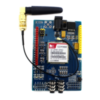
Details various onboard components and functionalities, including LEDs, buzzers, jumpers, connectors, and interfaces.

SIM900/900AGSM Modem PINOUT Description

Power Input and Enable

Describes the DC input jack and the power enable switch for turning the board ON or OFF.

Indicator LEDs and Buzzer

Details the functions of the power indicator LED, network indicator LED, and the buzzer for calls/messages.

Power ON Selection and Manual Control

Explains the jumper for power ON mode selection and the onboard switch for manual power control.

Communication and Interface Ports

Details DB9 serial connector, TTL interface header, audio pins, ADC, and PWM pins.

Network Indicator and Interface Details

Network Status Indicator LED Behavior

Describes the blinking patterns of the network indicator LED for different network states like not running or finding network.

ADC, PWM, Audio, SIM, and Vout Interfaces

Details ADC/PWM pins, audio interface, SIM card holder, and regulated voltage output.

SIM900/900A Modem Powering Modes

Automatic Power-ON Operation

Step-by-step guide to power ON the modem in automatic mode using jumpers and switches.

Manual Power-ON Operation

Step-by-step guide to power ON the modem in manual mode using jumpers, switches, or external signals.

Connecting SIM900A Modem to Computer

HyperTerminal Application Setup

Instructions for configuring the modem and launching the HyperTerminal application.

COM Port and HyperTerminal Settings

Guides on selecting the COM port and configuring HyperTerminal settings like baud rate and data bits.

Sending AT Commands to Modem

Serial Connection and Synchronization

Notes on establishing serial connection, initial synchronization strings, and receiving 'RDY'.

Basic AT Command Examples

Demonstrates sending basic AT commands like AT and ATI to interact with the GSM modem.

SIM900A Command Reference

ADC Commands (AT+CADC)

Details the AT+CADC=? test command and AT+CADC? read command for ADC functionality.

PWM Commands (AT+SPWM)

Explains AT+SPWM=? test command and AT+SPWM=<index>,<period>,<level> write command for PWM.