111
IT
ES
PT
GB
4.1 D.H.W. PRODUCTION
“BFT boiler - BT100 tank”
The preparation of hot water is guaranteed
by the glass storage tank unit with magne-
sium anode for the protection of the boiler
unit and inspection flange for its control and
cleaning. The magnesium anode must be
checked annually and substituted when it
is worn. It is advisable to place a sluice gate
at the entrance of the D.H.W. tank unit
which, apart from the total closure, allows
the regulation of the supply capacity.
If the boiler does not produce hot water,
make sure that the air has been released
by pressing on the manual vents after hav-
ing switched off the main switch.
4.2 ADJUSTMENT OF
D.H.W. FLOW RATE
To adjust the hot water flow rate, use the
flow-rate regulator on the pressure switch
valve (7 fig. 5). Remember that the flow
rates and corresponding temperatures of
use of hot water, given in section 1.3, have
been obtained by positioning the selector of
the circulation pump on the maximum value.
Should there be any reduction in the D.H.W.
flow rate, the filter installed on the inlet to
the pressure switch valve (3 fig. 5) will need
cleaning.
To access the filter, you must first
turn off the cold domestic water tap assem-
bled on the template.
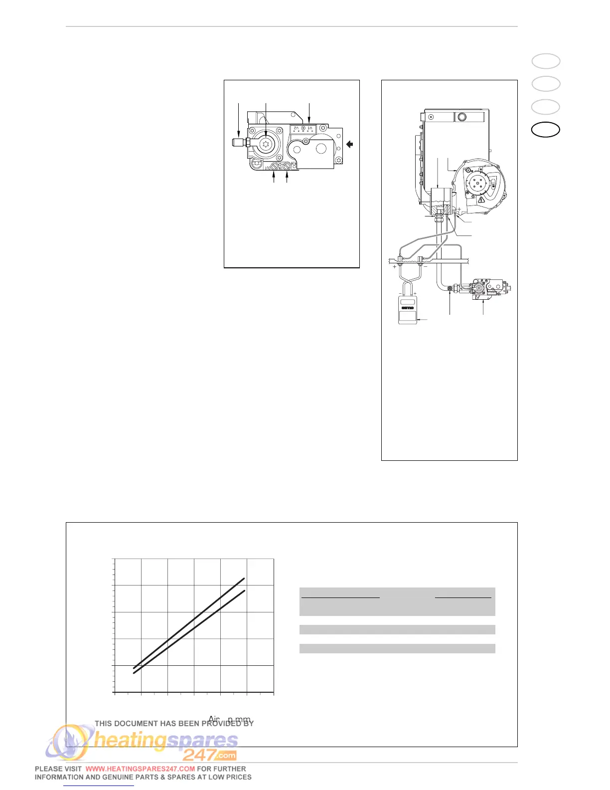
4.3 GAS VALVE
The boiler, is equipped standard with the
HONEYWELL VK 8115M gas valve (fig. 23).
4.4 ADJUSTMENT OF HEAT
OUTPUT FOR HEATING
To adjust boiler heat output for heating pur-
poses, i.e., modifying the setting made at the
factory which is approximately 17 kW, use a
screwdriver to adjust the heating heat out-
put trimmer (10 fig. 20).
To increase working pressure, turn the trim-
mer clockwise; to reduce pressure, turn the
trimmer counterclockwise.
To determine boiler heat output setting,
check energy consumption by observing the
meter and then compare with the values
shown in Tables 4 - 4/a - 4/b; or measure
“air ∆p” with a digital pressure gauge con-
nected up as shown in fig. 24.
Compare values with those shown in Tables
4 - 4/a - 4/b.
4 USE AND MAINTENANCE