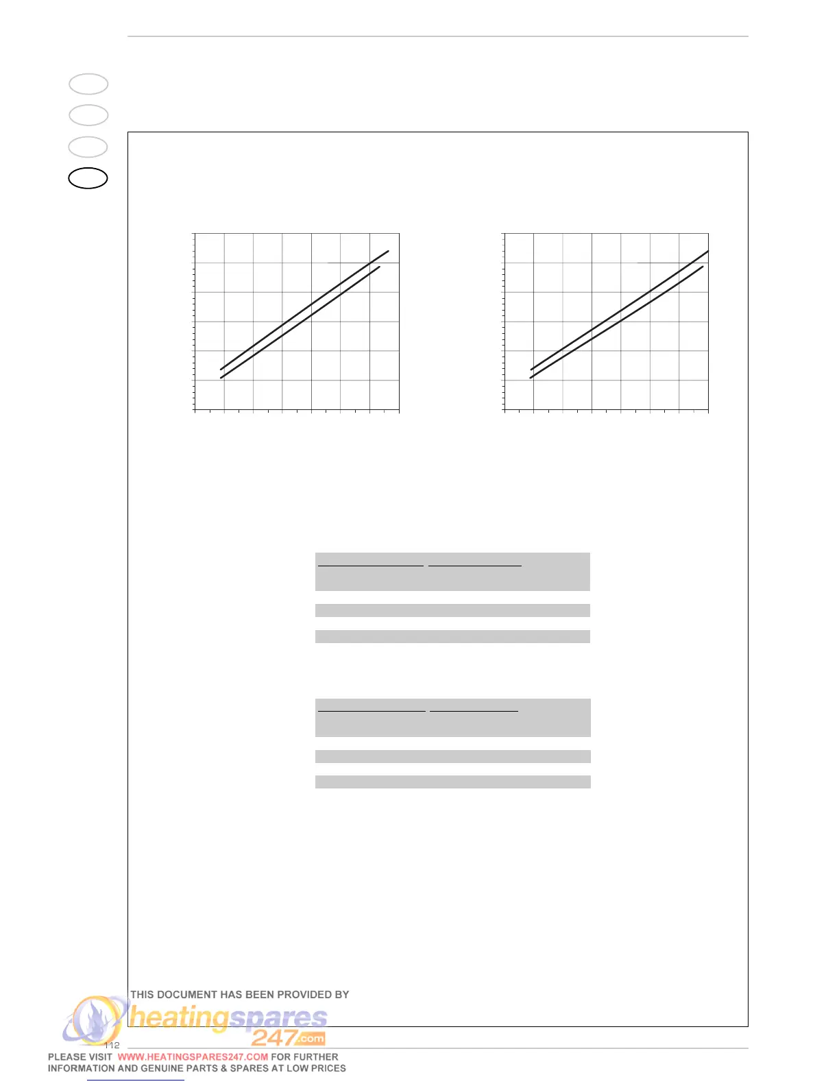
4.4.2 Diagram illustrating heat output in relation to “air ∆p” (“30” model)
Fig. 25/a
TABLE 4/a - G20
* Air ∆p is measured during boiler operation using a differential pres-
sure gauge connected to the ventilator intake.
** The gas consumptions refer to the calorific value at standard condi-
tions at 15°C - 1013 mbar.
Variable heat output Air ∆p*
Gas consum.
**
(80-60°C) (50-30°C) (80-60°C) (50-30°C) G20
kW kW mm H
2
O mm H
2
Om
3
/h st
29,3 32,0 63,8 66,4 3,17
22,9 25,0 45,0 45,0 2,48
16,1 17,6 25,0 25,0 1,75
10,4 11,4 8,4 9,2 1,14
TABLE 4/b - G31
Variable heat output Air ∆p*
Gas consum.
**
(80-60°C) (50-30°C) (80-60°C) (50-30°C) G31
kW kW mm H
2
O mm H
2
O kg/h
29,3 32,0 68,4 70,4 1,52
21,8 23,4 45,0 45,0 1,19
15,4 16,6 25,0 25,0 0,84
10,4 11,4 9,2 9,5 0,55
Heat outout (kW)
Air ∆p mm H
2
O
Heat outout (kW)
Air ∆p mm H
2
O