–
“25 BF - 30 BF” models: using the fill cock
on the pressure switch valve (2 fig. 5).
– “25 BFT - 30 BFT” model: using the fill
cock (29 fig. 2).
The charge pressure, with the system cold,
must be 1 bar.
Filling must be done slowly so as to allow
any air bubbles to be bled off through the air
valves.
When you have finished filling the system
close the fill cock.
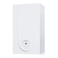
2.6 COAXIAL DUCT
ø 60/100
The air inlet-smoke outlet assembly, code
8096250, is included in the standard sup-
ply of the appliance complete with mounting
instructions.
2.6.1 Coaxial duct
accessories
The accessories to be used for this type of
installation and some of the connecting
systems that may be adopted are illustred
in fig. 6.
With the pipe bend included in the kit, the
maximum length of the piping should not
exceed 2.8 meter.
When the vertical extension code
8086950 is used, the terminal part of the
pipe must always come out horizontally.
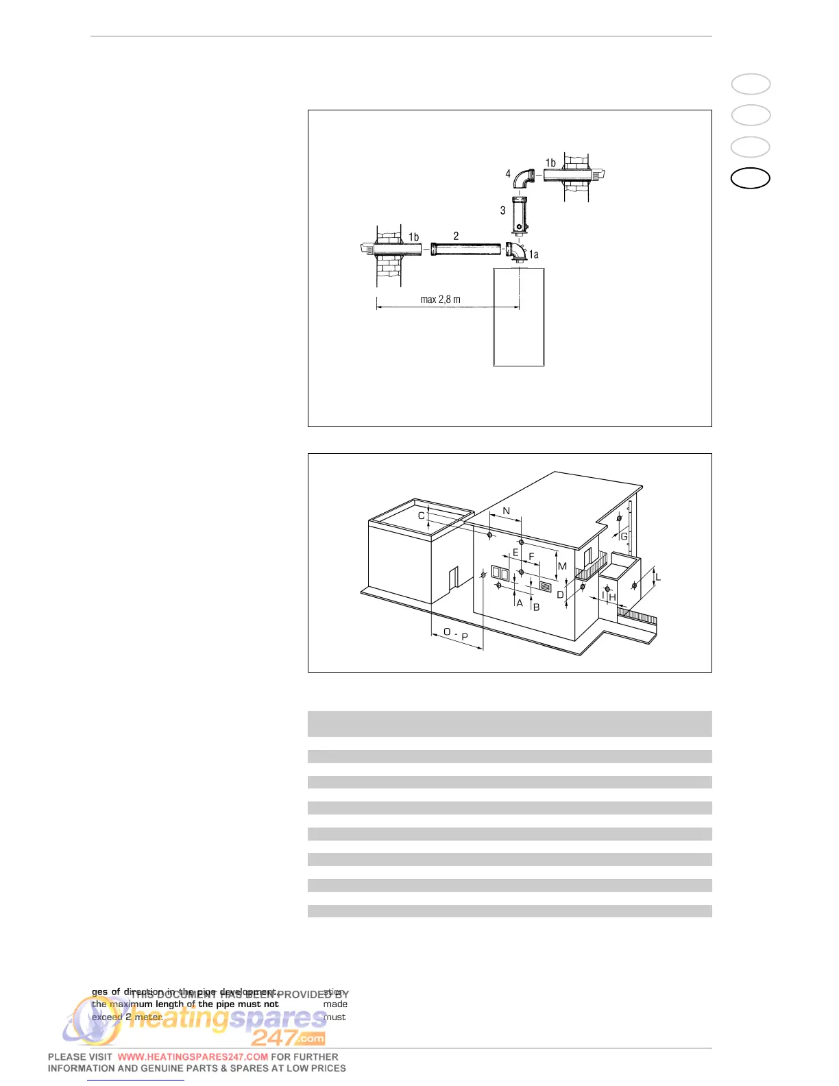
2.6.2 Positioning the
outlet terminals
The outlet terminals for forced-draught
appliances may be located in the external
perimeter walls of the building.
To provide some indications of possible solu-
tions, Table 1 gives the minimum distances
to be observed, with reference to the type
of building shown in fig. 7.
2.6.3 Coaxial duct outlet
on the roof
The roof discharge terminal L. 1285 cannot
be shortened and when positioning the tile,
the minimum distance from the discharge
head terminal must not be less than 600
mm (fig. 8).
The accessories to be used for this type of
installation and some of the connecting
systems that may be adopted are illustra-
ted in fig. 9.
It is possible to insert up to a maximum of
three extensions and reach a maximum
rectilinear distance of 3.7 meter.
Should it be necessary to make two chan-
ges of direction in the pipe development,
the maximum length of the pipe must not
exceed 2 meter.
99
IT
ES
PT
GB
Fig. 6
KEY
1a-b Coaxial duct kit code 8096250
2a Extension L. 1000 code 8096150
2b Extension L. 500 code 8096151
3 Vertical extension L. 140
with take-off point code 8086950
4a 90° additional bend code 8095850
4b 45° additional bend code 8095950
TABLE 1
Siting of terminal Appliances from 7 to 35 kW
(distances in mm)
A - below openable window 600
B - below ventilation opening 600
C - below eaves 300
D - below balcony (1) 300
E - from adjacent window 400
F - from adjacent ventilation opening 600
G - from horizontal or vertical soil or drain pipes (2) 300
H - from corner of building 300
I - from recess in building 300
L - from ground level or other treadable surface 2500
M - between two terminals set vertically 1500
N - between two terminals set horizontally 1000
O - from a surface facing without openings or terminals 2000
P - as above but with openings and terminals 3000
1)
Terminals below a practicable balcony must be located in such a way that the total path of
the smoke from its outlet point from the terminal to its outlet point from the external peri-
meter of the balcony, including the height of possible railings, is not less than 2000 mm.
2) When siting terminals, where materials that may be subject to the action of the combu-
stion products are present in the vicinity, e.g., eaves, gutters and downspouts painted or
made of plastic material, projecting timberwork, etc., distances of not less than 1500 mm
must be adopted, unless adequate shielding is provided to guard these materials.
Fig. 7
IMPORTANT:
Each additional 90° curve installed reduces the available length by 0.90 metres.
Each additional 45° curve installed reduces the available length by 0.45 metres.
NOTE
Before connecting accessories,
it is always advisable to lubricate
the internal part of the gaskets
with silicon products. Avoid using
oils and greases.
 Loading...