100
IT
ES
PT
GB
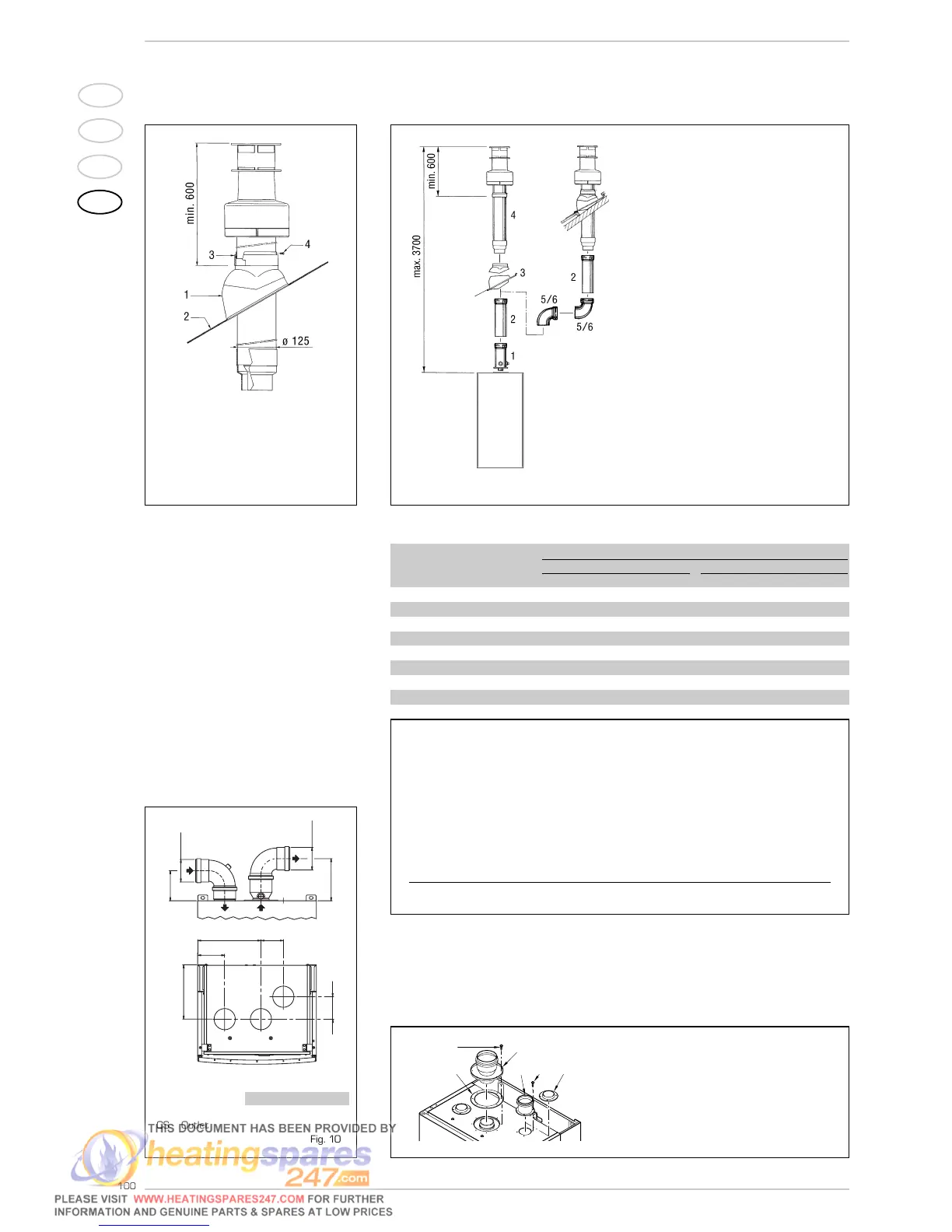
2.7 SEPARATE PIPES ø 80
A special kit may be used to separate the
flue gas outlet from the fresh air intake.
The intake may be installed to the right or
left of the flue gas outlet.
Both ducts may be oriented in any direction.
Refer to fig. 10 for positioning.
The maximum overall length of the intake
and exhaust ducts depends on the head
losses of the single fittings installed
(excluding the doublers) and must not be
greater than 12,5 mm H
2
O (“25” model)
and 15,5 mm H
2
O (“30” model).
For head losses in the fittings, refer to
Table 2.
2.7.1 Separate pipe
accessories
Kit code 8089911 is supplied for this pur-
pose (fig. 11).
The sectored diaphragm is to be used
according to the maximum head loss
allowed in both pipes, as given in fig. 12.
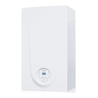
KEY
1 Tile with articulated joint
2 Lead panel
3 Collar
4 Locking screw
Fig. 8
Fig. 9
KEY
1 Vertical extension L. 140
with take-off points code 8086950
2a Extension L. 1000 code 8096150
2b Extension L. 500 code 8096151
3 Tile with articulation joint code 8091300
4 Roof outlet terminal L. 1285 code 8091205
5 Supplementary 90° elbow code 8095850
6 Supplementary 45° elbow code 8095950
Fig. 10
KEY
CA Inlet
CS Outlet
Example of allowable installation calculation (“25” version) in that the sum of the
head losses of the single fittings is less than 12,5 mm H
2
O:
Inlet Outlet
7 m horizontal pipe ø 80 x 0,20 1,40 –
7 m horizontal pipe ø 80 x 0,30 – 2,10
n° 2 90° elbows ø 80 x 0,30 0,60 –
n° 2 90° elbows ø 80 x 0,40 – 0,80
N° 1 terminal ø 80 0,10 0,30
Total head loss 2,10 + 3,20 = 5,3 mm H
2
O
TABLE 2
Accessories ø 80 Total head loss (
mm H
2
O)
“25” model “30” model
Inlet Outlet Roof outlet Inlet Outlet Roof outlet
90° elbow MF 0,30 0,40 – 0,30 0,50 –
45° elbow MF 0,20 0,30 – 0,20 0,40 –
Extension L. 1000 (horizontal) 0,20 0,30 – 0,20 0,40 –
Extension L. 1000 (vertical) 0,30 0,20 – 0,30 0,30 –
Outlet terminal – 0,30 – – 0,40 –
Inlet terminal 0,10 – – 0,10 – –
Doubler fitting 0,20 – – 0,30 – –
Roof outlet terminal L.1381 – – 0,50 – – 0,60
25 30
Z mm 220 190