101
IT
ES
PT
GB
2.7.2 Connection with existing flues
The ø 80 flue gas pipe may be connected to
an existing flue.
When the “PLANET DEWY” boiler is run-
ning at a low temperature, a regular flue
may be used under the following conditions:
– No other boiler must be using the flue.
–
The flue interior must be shielded
from direct contact with condensation
from the boiler.
The products of combustion must be
conveyed through a flexible or rigid pla-
stic pipe around 100 to 150 mm in dia-
meter, and condensation must be sipho-
ned off at the foot of the pipe.
The usable height of the water trap must
be at least 150 mm.
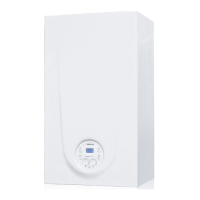
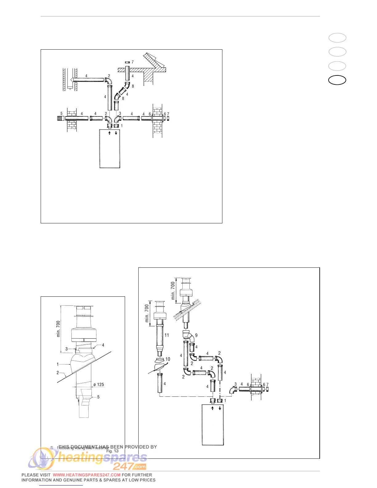
2.7.3 Separate-pipes roof outlet
The roof outlet terminal L. 1381 cannot be
shortened and when positioning the tile, the
minimum distance from the discharge head
terminal must not be less than 700 mm
(fig. 13).
The accessories to be used for this type of
installation and some of the connecting
systems that may be adopted are illustra-
ted in fig. 14.
There is the possibility of doubling the air-
intake and smoke-outlet pipes and then brin-
ging them back together again so as to
obtain a concentric discharge by using the
doubler fitting (9 fig. 14).
In these cases, when assembling, recover
the silicone gasket used on the terminal
adapter (5 fig. 13), which is to be replaced
by the doubler, and insert it into the seat
made in the doubler.
For this type of discharge the sum of the
maximum rectilinear development
allowed for the pipes must not exceed
12,5 mm H
2
O (“25” model) and 15,5
mm H
2
O (“30” model).
When calculating the lengths of pipe, take
into account the parameters given in the
Table 2.
KEY
1 Separate pipes kit code 8089911
2 90° elbow MF (6 pz.) code 8077450
3 90° elbow MF
with take-off points
code 8077452
4a Extension L. 1000 (6 pz.) code 8077351
4b Extension L. 500 (6 pz.) code 8077350
5 Outlet terminal code 8089501
6 Int.-est. ring kit code 8091500
7 Inlet terminal code 8089500
8 45° elbow MF (6 pz.) code 8077451
Fig. 12
Fig. 13
KEY
1 Tile with articulated joint
2 Lead panel
3 Collar
4
Locking screw
5 Reducing fitting with washer
Fig. 13/a
KEY
1 Separate pipes kit code 8089911
2 90° elbow MF (6 pz.)
code 8077450
3
90° elbow
MF wit htake-off points code 8077452
4 a Extension L. 1000 (6 pz.) code 8077351
4 b Extension L. 500 (6 pz.) code 8077350
6 Int.-est. ring kit code 8091500
7 Inlet terminal code 8089500
9 Doubler fitting code 8091400
10 Tile with articulated joint code 8091300
11
Roof outlet terminal L. 1381
code 8091204
NOTE
Before connecting accessories, it is always
advisable to lubricate the internal part of
the gaskets with silicon products. Avoid
using oils and greases.
NOTE
Before connecting accessories, it is
always advisable to lubricate the internal
part of the gaskets with silicon products.
Avoid using oils and greases.