2686
5
GB
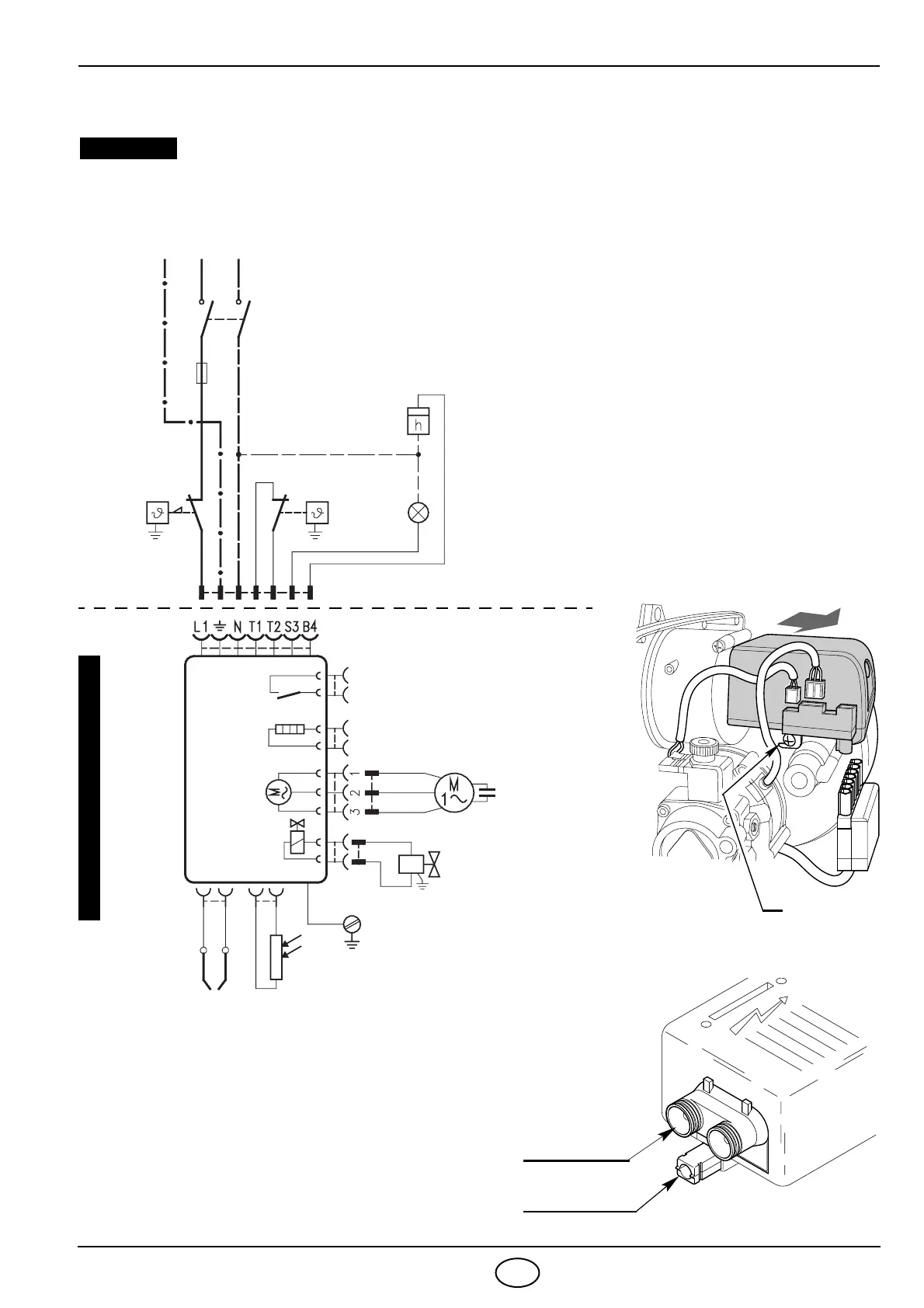
3.3 ELECTRICAL WIRING
TESTING
Check the shut-down of the
burner by opening the ther-
mostats.
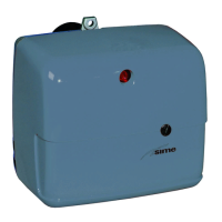
CONTROL BOX
To remove the control-box
from the burner, loosen screw
(A, fig. 8) and pull to the arrow
direction, after removing all
components, the 7 pin plug
and earth wire.
NOTES:
– Wires of 1 mm
2 section
.
– The electrical wiring carried out by the installer
must be in compliance with the rules in force in the
Country.
DO NOT EXCHANGE NEUTRAL WITH PHASE
WARNING
ACCESS TO THE PHOTORESISTANCE
(See fig. 9)
The
photoresistance is fitted directly into the con-
trol-box
(underneath the ignition-transformer)
on a
plug-in support.
Ignition
transformer
Fig. 9
E9102
Photoresistance
CARRIED-OUT IN THE FACTORY
7 pin plug
7 pole socket
Black
White
Blue
Capacitor
Burner-earth
T6A
CONTROL BOX
554SE
~ 50Hz 230V
D1846
Photoresistance
Oil valve
Hour counter
(230V - 0.1A max.)
Regulating
thermostat
Remote lock-out lamp
(230V - 0.5A max.)
Ignition
electrodes
LNPE
Motor
Main switch
Limit thermostat
with manual
resetting
Fig. 8
E9157
A