11
a)
The available pump head is given in fig. 20.
b) The burner starts when the C.H. flow
reaches 400÷450 l/h. This safety con-
dition is ensured by the flow switch.
c) The appliance is equipped with an inter-
nal by-pass that operates with system
heads (H) greater than 3 m. The maxi-
mum flow through the by-pass is about
300 l/h. If thermostatic radiator valves
are to be installed, at least one radiator
should be without a thermostatic valve
(usually the bathroom radiator).
d) A sealed system must only be filled by a
competent person using the filling loop
as shown in fig 5.
e) To fill the cylinder, open a DHW tap,
then turn on the domestic water supply.
When water runs from the tap turn it
off. Repeat at each DHW tap.
NOTE: there should be no isolation valve
fitted between the cylinder and the
expansion valve.
f) To drain the cylinder see fig. 2 number
23.
2.4.3 Discharge Pipes and fittings
The position of any tundish must be visible
to the occupants and any tundish, drain
valve and discharge pipe and must be sited
away from any electrical components.
The 7 and 3 bar PRV's are called out with
the number 15 and 22 on fig. 3.
The connections to the expansion relief
valve and temperature and pressure relief
valve should not be used for any other pur-
pose.
See fig. 6 for example of the discharge
pipe(s) for the temperature and pressure
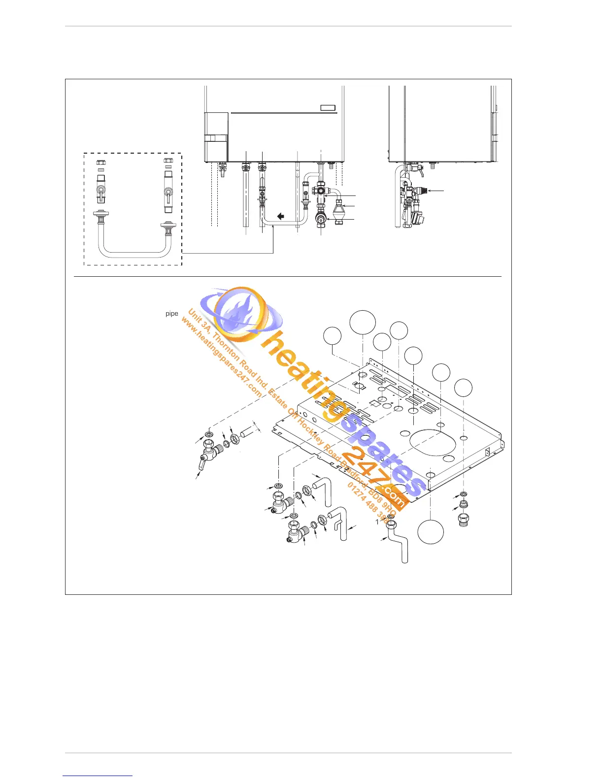
Fig. 5
KEY
1 Gasket ø 11,5/18,5 x 2
6 Gasket ø 17/24 x 2
8 Brass olive for 22 mm pipe
9 Locking nut 1-1/8”
10 Cock 3/4”
11 Flow regulator
12
Gas cock
13 Filling loop
14 Expansion relief valve
15 Tundish expansion relief valve
16 Single check valve
17 Pressure reducing valve
18 Curve return system
19 Curve flow system
20 D.H.W. outlet pipe
21 Brass olive for 15 mm pipe
22 Locking nut 1/2”
CONNECTIONS
G Gas inlet
M C.H. flow
R C.H. return
U D.H.W. outlet
E D.H.W. inlet
S3 Condensation outlet
DS 3 3 bar discharge
DS 7 7 bar discharge
DS 3
DS 7
No isolation valve should be fitted
between the cylinder and the
expansion valve.
 Loading...