12
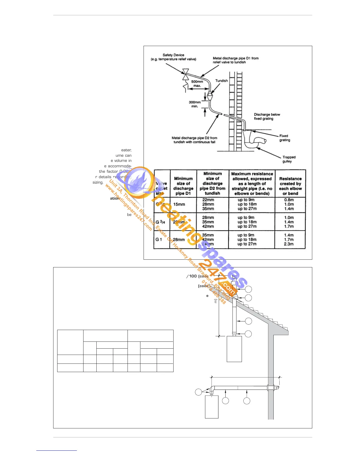
relief valve, and expansion relief valve termi-
nations.
Note: it is permitted to connect discharge
pipes together provided that the joint pipe
is sized to accommodate the combined
flow.
2.4.4 Expansion Vessel (C.H. only)
C.H. EXPANSION VESSEL – The integral
expansion vessel is pre-charged to a pres-
sure of 1.0 bar, which should be checked
before the C.H. water system is filled.
This vessel is suitable for correct operation
of system capacities up to 82 litre capacity.
If the actual C.H. system volume is greater,
then an additional vessel must be fitted to
the system.
For systems where the volume is greater,
the additional expansion vessel volume can
be determined by multiplying the volume in
excess of that which can be accommoda-
ted by the appliance by the factor 0.901.
BS 7074 gives further details regarding
C.H. expansion vessel sizing.
2.4.5 Connection of condensation
water trap
The drip board and its water trap must be
connected to a civil drain through a pipe
with a slope of at least 5 mm per metre to
ensure drainage of condensation water.
The plastic pipes normally used for civil
drains are the only type of pipe which is
appropriate for conveying condensation
to the building’s sewer pipes.
Fig. 6
Fig. 7
LIST OF ø 60/100 ACCESSORIES
1a-b
Coaxial duct kit L. 790 code 8096250
2a Extension L. 1000 code 8096150
2b Extension L. 500 code 8096151
3 Vertical extension L. 140 with coupling code 8086950
IMPORTANT:
- The insertion of each additional 90° bend with a diameter of 60/100 (code
8095850) reduces the available section by 1.5 meters.
- The insertion of each additional 90° bend with a diameter of 80/125 (code
8095870) reduces the available section by 2 meters.
- Each additional 45° curve installed a diameter of 60/100 (code 8095550) the
80/125 (code 8095970) reduces the available length by 1.0 metres.
- During assembly it is important to make sure that the kit with axial pipes (1) is posi-
tioned HORIZONTAL FLUES MUST BE LEVEL..
NOTE: Before connecting accessories, it is always advisable to lubricate the internal
part of the gaskets with silicon products. Avoid using oils and greases.
Model Length of pipe Length of pipe
ø 60/100 ø 80/125
HV HV
Min Max Min Max
25/55 6 m 1.3 m 8 m 12 m 1.2 m 15 m
30/55 5 m 1.3 m 7 m 10 m 1.2 m 13 m
LIST OF ø 80/125 ACCESSORIES
1a-b Coaxial duct kit L. 785 code 8096253
2a Extension L. 1000 code 8096171
2b Extension L. 500 code 8096170
3 Adapter for ø 80/125 code 8093150
V (VERTICAL - m)
H (HORIZONTAL - m)
 Loading...