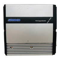
SRM9000 ALIGNMENT TNM-M-E-0019 Issue 1
Page 2 of 13
Black
Red
Yellow
Blue
Brown
Orange
Green(4)
White (8)
(Not Used)
+
470E
White
Green
Mic Audio in
Mic Ground
Ground
Handset AF Output
13.8V Switched
On/Off
Rx Data
Tx Data
8
4
7
6
5
3
2
1
RJ45
PRM80
Programming Cable
P/N 9525-001-00016
BNC (F)
Connector
22uF to 47uF
Tant. or Elect
DB25
ccess and modify
cable as shown
9000_49/2
2
5
-
9
W
a
y
A
d
a
p
t
o
r
PC
To
SRM9000
S1
F Generator
R
Figure 0 SRM9000 Programming & Alignment Breakout Box
.
.
.
To
SRM9000 P2
Pins 6 & 13
R = Audio power Load (set as appropriate)
or
Resistor 4R 4W for ½ Bridge Speaker option
Resistor 8R 12W for full Bridge Speaker option
600R 1:1
Line Matching
Transformer
To
Noise & Distortion Meter
&
Oscilloscope
9000_49/3b
R
T1
Figure 1 SRM9000 Speaker Output Breakout Box