RELAY TERMINALS
TO 6053 SUPERVISED REMOTE
RESISTOR
INTERFACE MODULE
SUPERVISORY
TO 6053 SUPERVISED REMOTE
INTERFACE MODULE
+V OUT TO 6053 SUPERVISED REMOTE
INTERFACE MODULE WHEN MIKE SWITCH
PRESSED
PLUG
P2 DISCONNECTED:
RESISTANCE BETWEEN
TERMINALS TBl-1 AND TBl-2 WHEN
MIKE SWITCH RELEASED; 200 OHMS
RESISTANCE BETWEEN TERMINALS
TBl-1 AND TBl-2 WHEN MIKE SWITCH
PRESSED
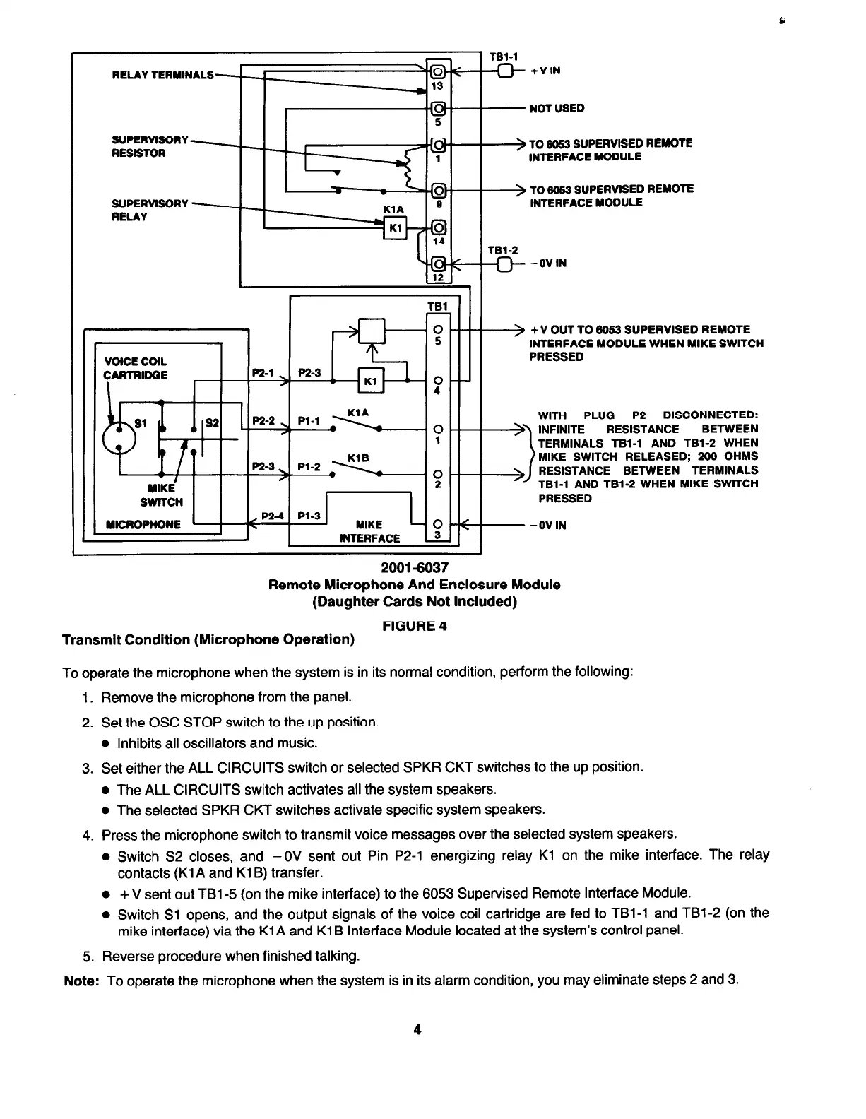
2001-6037
Remote Microphone And Enclosure Module
(Daughter Cards Not Included)
FIGURE 4
~_ _
Transmit Condition (Microphone Operation)
To operate the microphone when the system is in its normal condition, perform the following:
1. Remove the microphone from the panel.
2. Set the OSC STOP switch to the up position.
l
Inhibits all oscillators and music.
3. Set either the ALL CIRCUITS switch or selected SPKR CKT switches to the up position.
l
The ALL CIRCUITS switch activates all the system speakers.
l
The selected SPKR CKT switches activate specific system speakers.
4. Press the microphone switch to transmit voice messages over the selected system speakers.
l
Switch S2 closes, and -0V sent out Pin P2-1 energizing relay Kl on the mike interface. The relay
contacts (Kl A and Kl B) transfer.
l
+ V sent out TBl-5 (on the mike interface) to the 6053 Supervised Remote Interface Module.
l
Switch Sl opens, and the output signals of the voice coil cartridge are fed to TBl-1 and TBl-2 (on the
mike interface) via the KlA and Kl B Interface Module located at the system’s control panel.
5. Reverse procedure when finished talking.
Note:
To operate the microphone when the system is in its alarm condition, you may eliminate steps 2 and 3.
4
 Loading...