2
2001-6037 REMOTE MICROPHONE AND ENCLOSURE MODULE DESCRIPTION
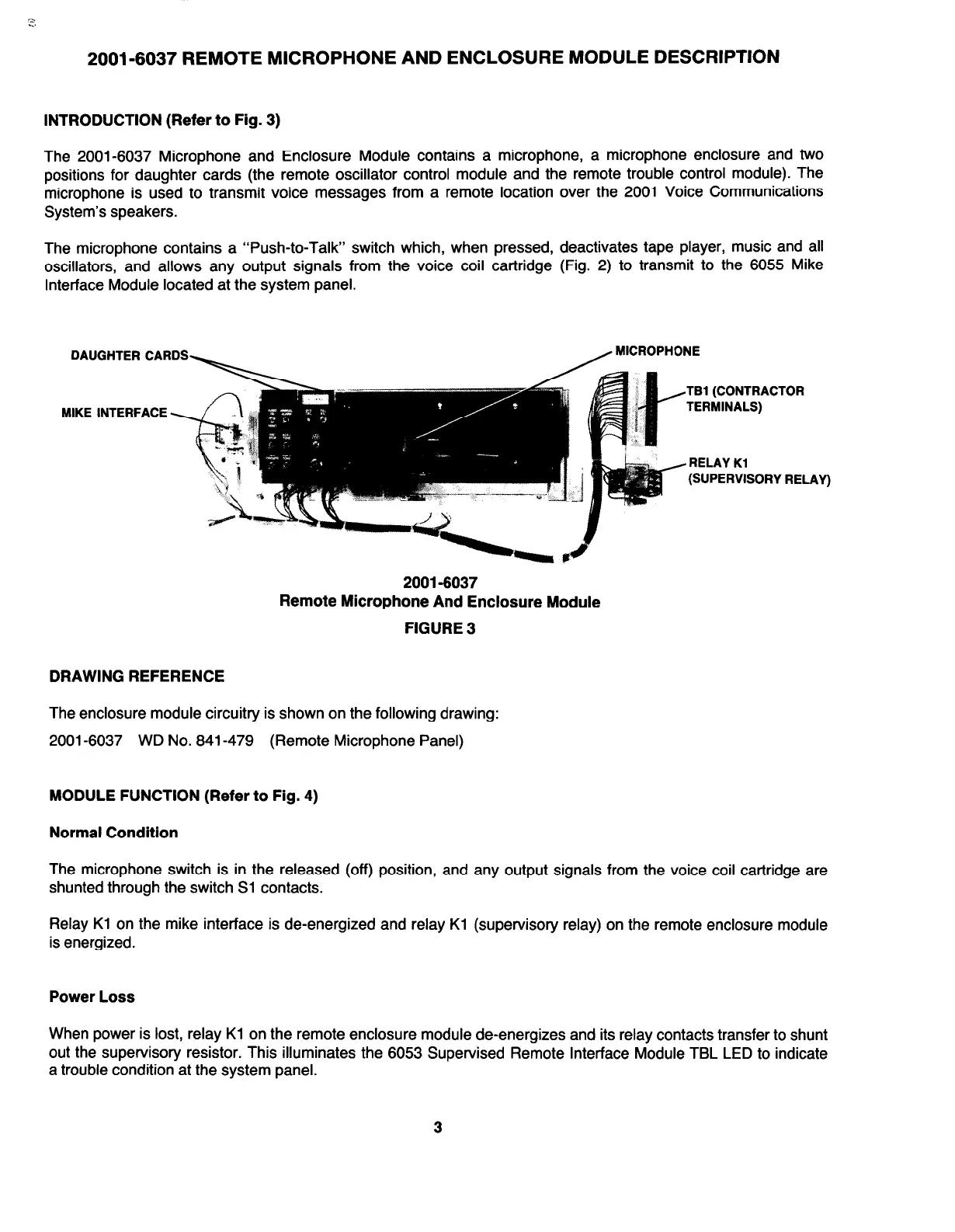
INTRODUCTION (Refer to Fig. 3)
The 2001-6037 Microphone and Enclosure Module contains a microphone, a microphone enclosure and two
positions for daughter cards (the remote oscillator control module and the remote trouble control module). The
microphone is used to transmit voice messages from a remote location over the 2001 Voice Communications
System’s speakers.
The microphone contains a “Push-to-Talk’ switch which, when pressed, deactivates tape player, music and all
oscillators, and allows any output signals from the voice coil cartridge (Fig. 2) to transmit to the 6055 Mike
Interface Module located at the system panel.
DAUGHTER CARDS
MIKE INTERFACE
MICROPHONE
TBl (CONTRACTOR
TERMINALS)
RELAY Kl
(SUPERVISORY REL
.AY)
2001-6037
Remote Microphone And Enclosure Module
FIGURE 3
DRAWING REFERENCE
The enclosure module circuitry is shown on the following drawing:
2001-6037 WD No. 841-479 (Remote Microphone Panel)
MODULE FUNCTION (Refer to Fig. 4)
Normal Condition
The microphone switch is in the released (off) position, and any output signals from the voice coil cartridge are
shunted through the switch Sl contacts.
Relay Kl on the mike interface is de-energized and relay Kl (supervisory relay) on the remote enclosure module
is energized.
Power Loss
When power is lost, relay Kl on the remote enclosure module de-energizes and its relay contacts transfer to shunt
out the supervisory resistor. This illuminates the 6053 Supervised Remote Interface Module TBL LED to indicate
a trouble condition at the system panel.
3
 Loading...