2
Module
Overview
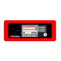
Refer to Figure 1 for the remote annunciator front view and to Figure 2 for the back layout.
Figure 1. Remote Annunciator Front View
Figure 2. Remote Annunciator Back View
Table 1. Remote Annunciator Main Back Components
Serial Service
Port (P2)
Not yet available. Future use.
USB port (P5) Allows downloading fonts and MsgLib information. To access the USB port,
remove the trim plate and then unscrew the annunciator from the back box
(see Figure 6). For more information about the thumb drive, refer to the
Programmer’s Manual, 579-1167.
Address
Switch (SW-2)
Sets FACP address and communications online or offline.
Reset Switch
(SW1)
Short press (< 5 seconds) to activate a software reset (warm start).
Press and hold (> 5 seconds) to force a hardware reset (warm start).
Unless the annunciator CPU appears to be locked up, the software
controlled reset should be used. A warm start preserves the logs and the
disabled status of points in the disabled state.
Service Mode
Jumper
To access the service mode jumper, the cover plate needs to be removed.
IMPORTANT: Factory use only. Do not remove.
Piezo
Power LED
Touchscreen
Bi-Color User
Defined LEDs
Slide-in Labels
Keyswitch
Supervisory LED
Priority 2 LED
Fire LED
Alarm Silenced LED
Trouble LED
ON
OFF
1 2 3 4 5 6 7 8
USB Port
Serial
Service Port
Reset Switch
Ground
Harness
TB1
Address Switch
Color Touchscreen LCD Annunciator Installation Instructions, Continued

 Loading...