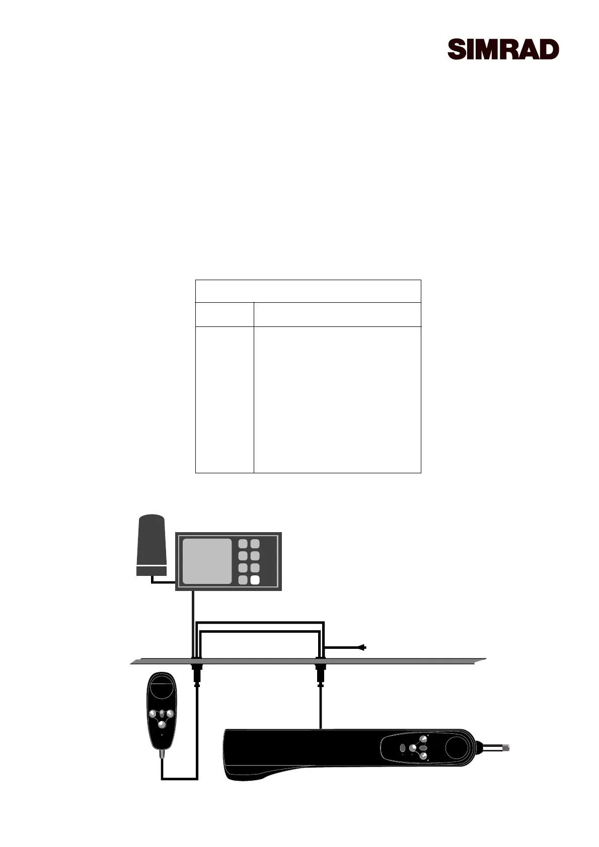
12v DC
NMEA (Yellow / Blue)
Power (Red / Black)
NMEA
(Green / White)
NAV
STBY
TACK
STBY
AUTO
STBY
TACK
STBY
AUTO
Fig 6 - Autopilot / Navigational
Receiver / Autopilot Schematic
Installation & Wiring
The HR20 is linked to the Autopilot via its NMEAinput terminals. To enable a neat installation, the HR20 is sup-
plied with a 4-way bulkhead socket and cable assembly. This is connected to the power supply, and to the NMEA
terminals of the Autopilot.
If a GPS / Navigational Receiver is already interfaced to the Autopilot via the NMEAterminals, these wires should
be disconnected and re-linked to the green (Com) and white (Data) wires of the Hand Remote socket assembly (Fig
6). The blue and yellow wires should be connected to the NMEACom and Data terminals respectively of the
Autopilot to replace the removed NMEAcable. The red and black wires should be connected to a 12v supply cable.
Note that the Autopilot and NMEAlink will still function with the HR20 unplugged.
E03550 Issue 1.0 CLICK HERE TO RETURN TO SERVICE MANUAL
4 Pin Socket Wiring
Wire Wire To
Green NMEACom from GPS*
White NMEAData from GPS*
Red 12v+ DC
Black 0v
Blue NMEACom - Autopilot
Yellow NMEAData - Autopilot
* GPS or other NMEA0183 compatible
Navigational Receiver