2/4
4 x 1,5mm
2
4 x 1,5mm
2
L1 L2 L3
U WV
L1 L2 L3
WV
U
652
1
3 4
6 x 1,5mm
2
moteur/motor
1
2
Alimentation triphasée 400V :
- Vérifier la présence du pont 1
- Phases L1 - L2 - L3
- Terre (vert/jaune) raccordée au domino (livré avec le
coffret).
Moteur triphasé 400V :
- Sortie moteur U - V - W
- Terre (vert/jaune) raccordée au domino (livré avec le
coffret).
Attention : Vérifier le câblage au niveau du bornier
moteur.
câblage étoile : 400V triphasé (voir notice
motorisation)
3 phases power supply 400V:
- Check the bridge 1
- Phases L1 - L2 - L3
- Earth (green / yellow) connected to a connecting block
(delivered with the box)
3 phases motor 400V:
- Motor output U - V - W
- Earth (green / yellow) connected to connecting block
(delivered with rhe control box).
Caution: Check the wiring on the motor terminals
Star connection: 400V three-phases (refer to
motor instruction sheet).
Préconisations de câblage
-
Dans le cas ou vous n’utilisez pas l’entrée “Stop” laissez
le pont 2 en place.
- Les fils vert/jaune des câbles servent uniquement au
raccordement de la terre. Ils ne doivent par conséquent,
en aucun cas, être utilisés pour d’autres applications.
- Afin de préserver l’étanchéité du coffret, ne passez
qu’un seul câble par presse-étoupe et vérifiez le serrage
de ce dernier.
- En cas de mauvais sens de rotation du moteur, inverser
les fils V et W.
Recommendations of wiring
-
In the case of you don’t use a high safety nor "Stop"
button, don’t remove the bridge 2.
- The wire green/yellow are used only for connection of
the ground. Consequently, they do not have used for
other applications.
- In order to preserve the sealing of the box, pass one
cable by stuffing box and check the tightening of this
piece.
- In the event of bad direction of rotation of the motor,
to reverse the wire V and W.
1 - 2 (NF) : fi
n de course haut.
3 - 4 (NF) : fi
n de course bas.
5 - 6 (NF) : protection thermique.
1 - 2 (NC): UP end limit
3 - 4 (NC): DOWN end limit
5 - 6 (NC): Thermal probe.
Pour toute manipulation à l’intérieur du coffret, suivre les
instructions suivantes :
- Dévisser les 2 vis situées à gauche du cof
fret
- Dévisser à mi-course les 2 vis de droite
- Ouvrir doucement le couvercle du coffret, les 2 vis de
droite servant de charnière
- Débrancher l’interface de liaison en tenant le connecteur
noir et en tirant légèrement vers vous.
Attention :
- ne pas tirer directement sur la liaison.
-
Pour faciliter le branchement, lors de la mise en service
du coffret, enlever le couvercle et utiliser le tournevis
fourni avec le coffret.
- Pour rebrancher le connecteur noir : orienter le repère
blanc placé sur la tranche du connecteur vers le repère
J8 de la carte électronique.
- Si le clavier est connecté à l’envers, la carte
électronique ne sera pas endommagée mais le clavier
ne fonctionnera pas.
For any handling inside the box, please follow hereafter
instructions :
- unscrew the 2 screws located on left of the box
- unscrew half way the 2 screws on right
- Open carefully the cap of the box, the 2 screws on the
right as hinges
- Plug out the linking interface : hold the black connector
and pull slightly.
Caution:
- do not pull dir
ectly on the linking interface.
- To ease the connection during the assembly of the
control box, remove the cap and use the screwdriver
delivered with the control box.
-
To connect again the black connector : adjust the white
mark located on the side of the connector to the mark J8
of the electronic relay board.
- If the keyboard is connected in the bad way, the
electronic card will not be damaged but the keyboard
will not work.
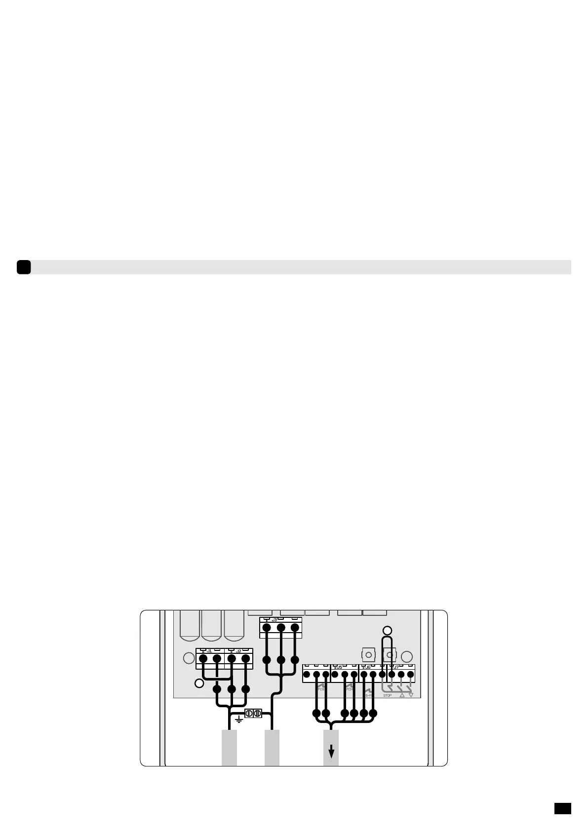
Câblage du SIMUDRIVE 250 avec un moteur triphasé - Simudrive connection with a three phases motor
3
 Loading...