5/8
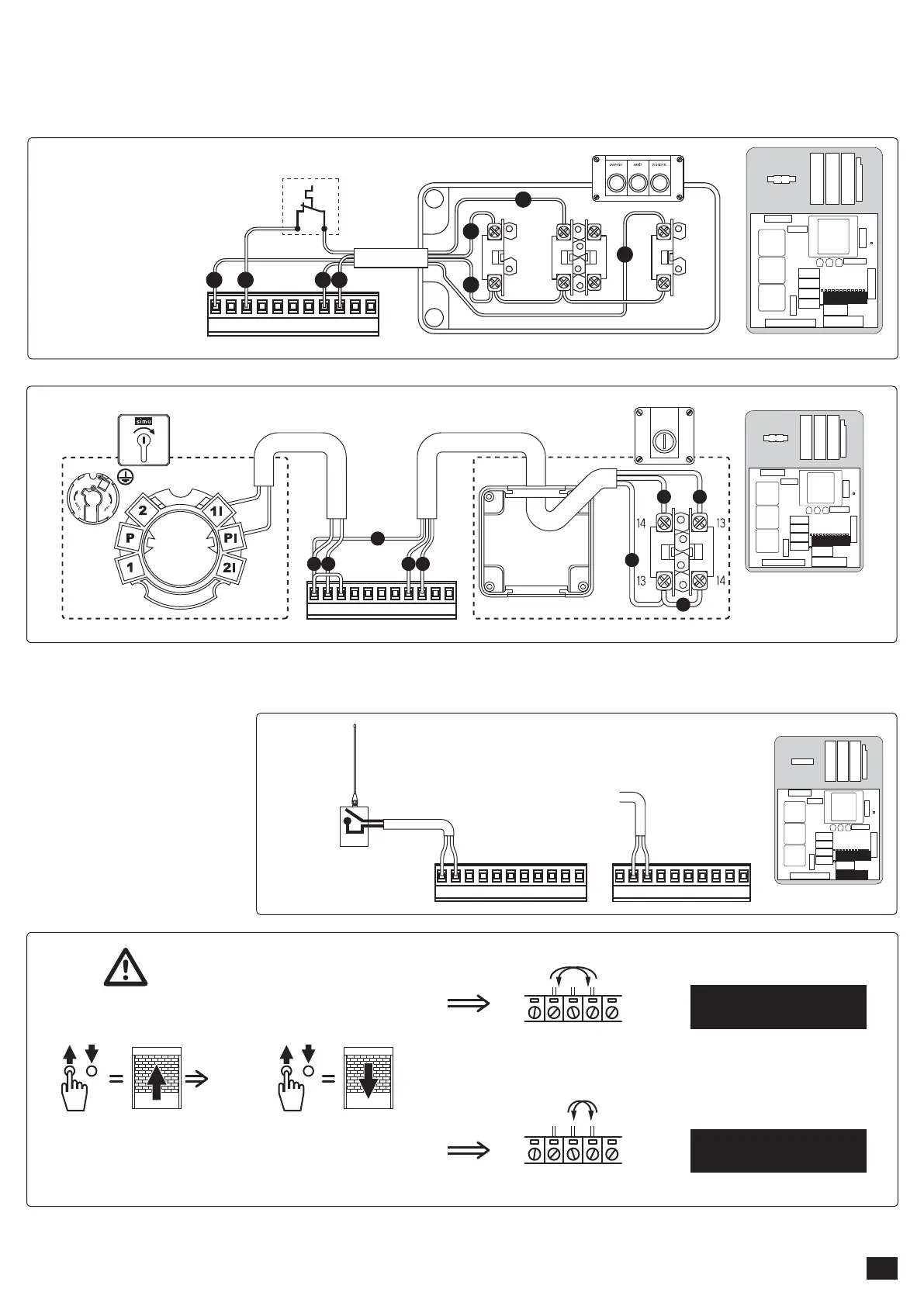
3.6 - Connection of control devices:
3.6.1 - wired controls (the push button on the cover are delivered wired: 26 : common, 33 : open, 34 : close):
- Example of cabling with impulse key switch (2004964):
- Example of connection with a 3 buttons switch (1850046):
26 - 27 = Start (NO)
26 - 28 = Stop (NF)
26 - 33 = Open (NO)
26 - 34 = Close (NO)
3.6.2 - Radio control:
11 & 12 = 24Vac Power supply
26 = common
27 = Start
26 27 28 29 30 31 32 33 34 35 36
433MHz RECEIVER
24 Vac POWER SUPPLY
NO
JP2JP4
10 11 12 13 14 15 16 17 18 19
26 27 28 29 30 31 32 33 34 35 36
UNIVERSAL KEY SWITCH UNSTABLE ROTARY SWITCH
M
N1 N2
M
M
N1 N2P 1
JP4
11
12 14
13
13
13
14
14
26 27 28 29 30 31 32 33 34 35 36
MOTOR THERMAL PROBE
M
M
N1
N1
N2
N2
B
B
JP4
Test: direction of rotation
OK
JP1
567
S1 N S2
JP1
5 6 7
M1 M2 M3
SINGLE PHASE MOTOR
230V - 50Hz
THREE-PHASES MOTOR
400V - 50Hz