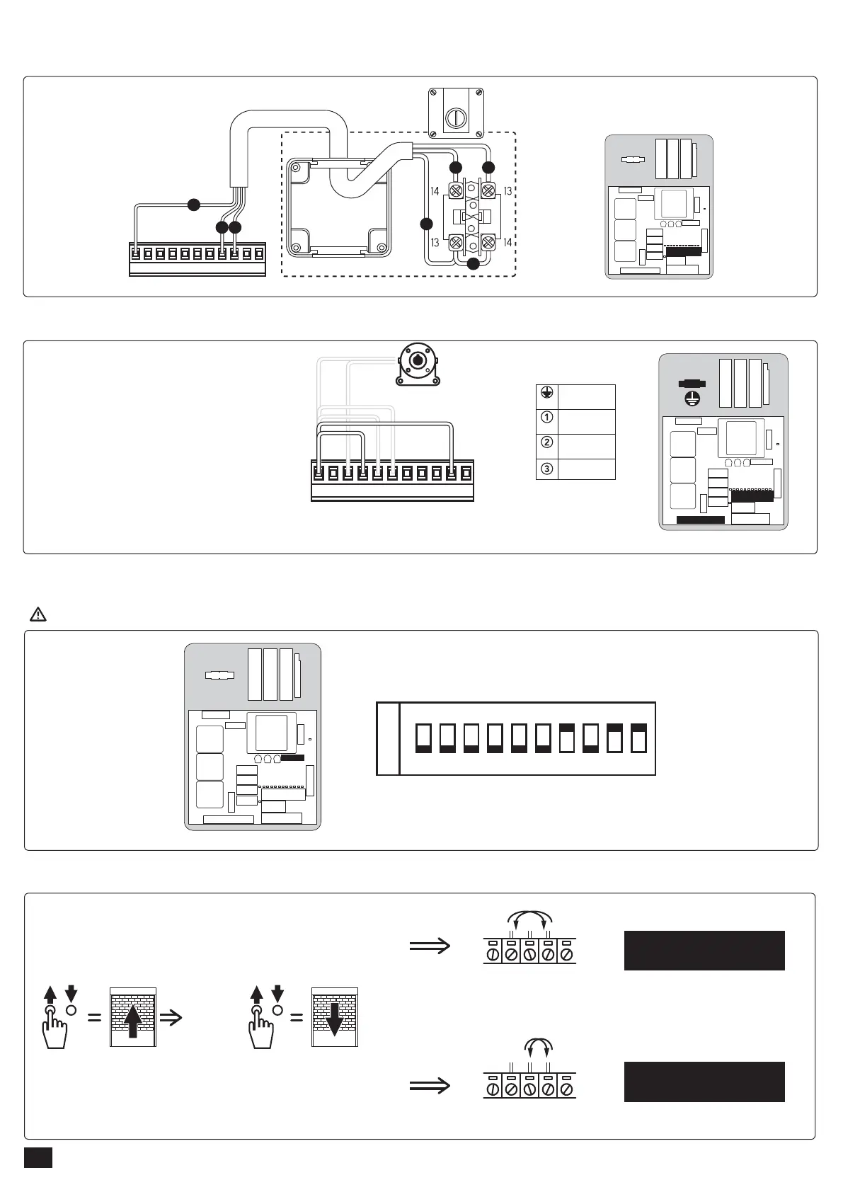
3.7.2 - Set up of the bridges
3.7.3 - Contact programming:
3.7.4 - Direction test
Install bridges between 26 and 29
and between 26 and 35
Be careful, no change should be performed on the default programming of the micro-contact.
26 27 28 29 30 31 32 33 34 35 36
Make bridges between connectors:
26 and 29
26 and 35
GREEN / YELLOW
230V-50Hz
BLUE
BROWN
BLACK
PE
N
L
SAFETY BRAKE
Any programming change will make the installation non-compliant.
26 27 28 29 30 31 32 33 34 35 36
UNSTABLE ROTARY SWITCH
M
N1 N2
M
M
N1 N2
JP4
3.7 - Cabling in “maintained push” mode
3.7.1 - Cabling with unstable rotary switch (unstable key switch) (2001548) (2006754) :
OK
JP1
567
S1 N S2
JP1
5 6 7
M1 M2 M3
SINGLE PHASE MOTOR
230V - 50Hz
THREE-PHASES MOTOR
400V - 50Hz
6/8