SINAMICS G120
Standard inverters 0.37 kW to 250 kW (0.5 hp to 400 hp)
PM240 Power Modules –
0.37 kW to 250 kW (0.5 hp to 400 hp)
4/32
Siemens D 11.1 · 2009
4
■
Integration
PM240 Power Modules communicate with the Control Unit via
the PM-IF interface.
PM240 Power Modules have the following interfaces as stan-
dard:
• PM-IF interface to connect the PM240 Power Module to the
Control Unit. The PM240 Power Module also supplies power to
the Control Unit using an integrated power supply
• Terminals DCP/R1 and R2 for connection of an external bra-
king resistor, valid up to frame size FSF. For frame size FSGX,
an external plug-in braking unit (Braking Module) is required
to connect a braking resistor
• Motor connection using screw terminals or screw studs
• Control for the Brake Relay or the Safe Brake Relay for control-
ling a motor brake
• 2 PE/protective conductor connections
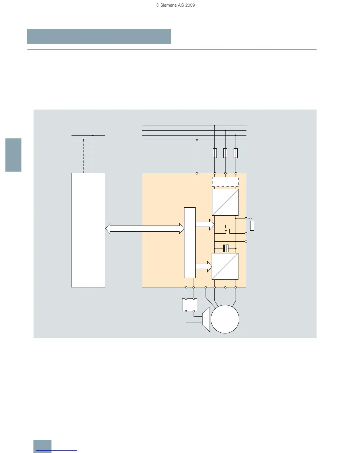
PM240 Power Module connection diagram with or without integrated class A line filter
380 V to 480 V 3 AC
Line filter
class A
Braking
resistor
1)
G_D011_EN_00100b
Motor brake
PM-IF Interface
ext. 24 V DC or via
Power Module
required
1)
For frame size FSGX
a Braking Module is required
for connecting a braking resistor
24 V
0 V
L1
L2
L3
PE
PE
U1/
L1
V1/
L2
W1/
L3
~
3
=
Power Module
PM240
Control Unit
=
~
3
W2V2U2PEBA
Brake
Relay
~
3
M
DCP/R1
DCN
R2
 Loading...