SINAMICS G120
Standard inverters 0.37 kW to 250 kW (0.5 hp to 400 hp)
PM250 Power Modules –
7.5 kW to 75 kW (10 hp to 100 hp)
4/54
Siemens D 11.1 · 2009
4
■
Integration
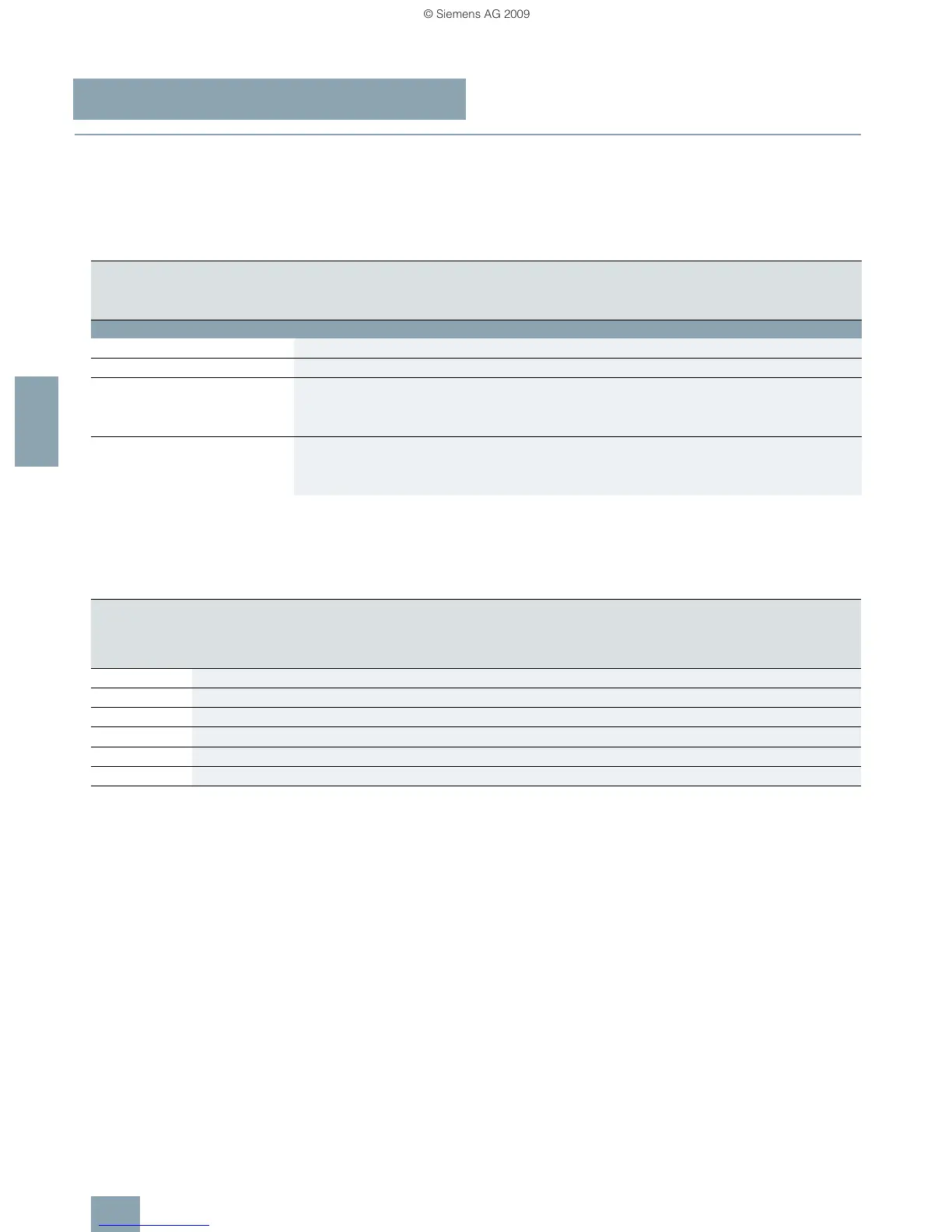
Maximum permissible cable lengths from the motor to the
inverter when using output reactors or sine-wave filters
depending on the voltage range
The following load-side power components in the appropriate
frame sizes are optionally available for the Power Modules and
result in the following maximum cable lengths:
Derating data
The following inverter output currents can still be implemented
for long motor cables without output reactor and sine-wave filter.
Derating for PM250 Power Modules, frame sizes FSC to FSF for
shielded motor cables. From frame size FSD and higher, only the
particular main Power Module types were tested. The values
also apply to the other Power Modules of the particular frame
size.
– Not possible
Maximum permissible motor cable lengths (shielded/unshielded) in m
Frame sizes
FSA FSB FSC FSD FSE FSF FSGX
PM250 Power Module with line-commutated energy recovery
Available frame sizes – – ✓ ✓ ✓ ✓ –
Without output reactor/sine-wave filter – – 50/100 50/100 50/100 50/100 –
With optional output reactor
• at 380 V (–10 %) to 400 V 3 AC – – 150/225 200/300 200/300 200/300 –
• at 401 V to 480 V (+10 %) 3 AC – – 100/150 200/300 200/300 200/300 –
With optional sine-wave filter
• at 380 V (–10 %) to 400 V 3 AC – – 200/300 200/300 200/300 200/300 –
• at 401 V to 480 V (+10 %) 3 AC – – 200/300 200/300 200/300 200/300 –
Rated power
(at I
H
)
Frame size Base load
current I
H
Rated output
current I
rated
Motor con-
nection cross-
section
Current derating
of the output current as a % of the base load current
for the cable lengths (MOTION-CONNECT)
kW hp A A mm
2
50 m 100 m 150 m 200 m
5.5 7.5 FSC 13.2 18 10 100 % 70 % 45 % –
7.5 10 FSC 19 25 10 100 % 90 % 80 % –
11.0 15 FSC 26 32 10 100 % 90 % 80 % –
22.0 30 FSD 45 60 35 100 % 95 % 90 % 85 %
37.0 50 FSE 75 90 35 100 % 100 % 95 % 90 %
75.0 100 FSF 145 178 95 100 % 100 % 100 % 95 %
 Loading...