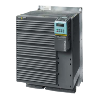
SINAMICS G120
Standard inverters 0.37 kW to 250 kW (0.5 hp to 400 hp)
PM260 Power Modules –
11 kW to 55 kW (15 hp to 75 hp)
4/70
Siemens D 11.1 · 2009
4
■
Technical specifications
Line supply voltage
500…690V3AC
PM260 Power Modules
Without integrated line filter 6SL3225-0BH32-2UA1 6SL3225-0BH33-0UA1 6SL3225-0BH33-7UA1
With integrated line filter 6SL3225-0BH32-2AA1 6SL3225-0BH33-0AA1 6SL3225-0BH33-7AA1
Output current at
50 Hz 690 V 3 AC
• Rated current I
rated
1)
A 35 42 62
• Base load current I
L
1)
A 35 42 62
• Base load current I
H
2)
A 26 35 42
• I
max
A 52 70 84
Rated power
• based on I
L
kW (hp) 30 (40) 37 (50) 55 (75)
• based on I
H
kW (hp) 22 (30) 30 (40) 37 (50)
Rated pulse frequency
kHz 16 16 16
Efficiency
η
0.95 0.95 0.95
Power loss
(at rated current)
kW 1.13 1.29 1.73
Cooling air requirement m
3
/s 0.131 0.131 0.131
Sound pressure level L
pA
(1 m)
dB <70 <70 <70
24 V DC power supply for
Control Unit
A 1 1 1
Input current
3)
• Rated current A 34 41 60
• based on I
H
A 26 34 41
Line supply connection
U1/L1, V1/L2, W1/L3
M6 screw studs M6 screw studs M6 screw studs
• Conductor cross-section mm
2
10 … 50 10 … 50 10 … 50
Motor connection
U2, V2, W2
M6 screw studs M6 screw studs M6 screw studs
• Conductor cross-section mm
2
10 … 50 10 … 50 10 … 50
PE connection On housing with M6 screw On housing with M6 screw On housing with M6 screw
Motor cable length, max.
4)
• Shielded m 200 200 200
• Unshielded
m 300 300 300
Degree of protection
IP20 IP20 IP20
Dimensions
• Width mm 350 350 350
•Height mm 634 634 634
•Depth
- without Control Unit mm 316 316 316
- with Control Unit mm 372 372 372
Frame size FSF FSF FSF
Weight, approx.
• without integrated filter kg 56 56 56
• with integrated filter kg 58 58 58
1)
The rated output current I
rated
and the base load current I
L
are based on
the duty cycle for light overload (LO).
2)
The base load current I
H
is based on the duty cycle for high overload (HO).
3)
The input current depends on the motor load and is valid for a line impe-
dance corresponding to u
K
= 1 %. The rated input currents apply for a load
at the rated power (based on I
rated
) – these current values are specified on
the rating plate.
4)
Shielded motor cables must be used in order to maintain the limit values
for field-conducted disturbances according to EN 61800-3 Class C2.
 Loading...