DC INVERTER U-MATCH AIR CONDITIONERS INSTALLATION
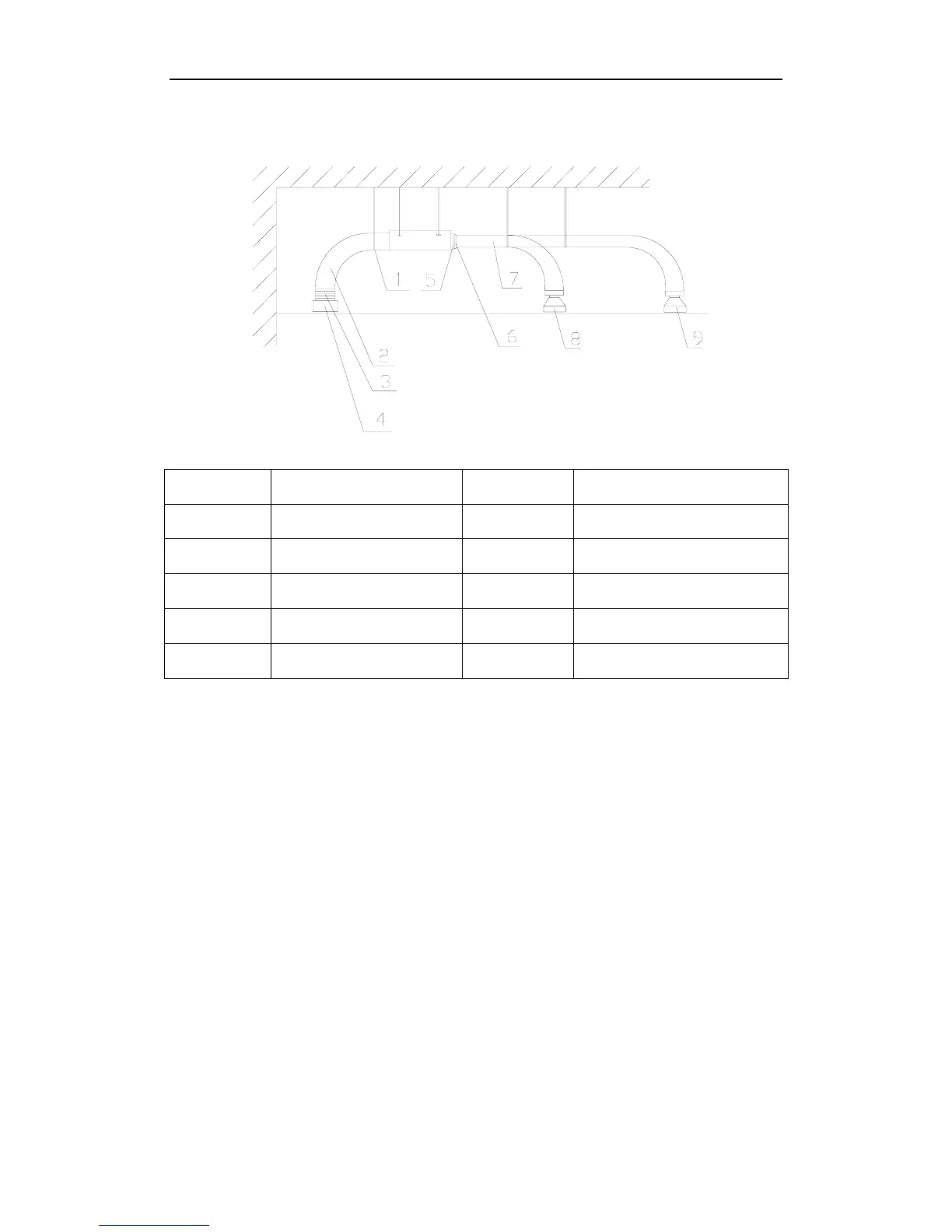
Installation of round air duct, as shown in Fig. 1-1-12
Figure 1-1-12
Number Name Number Name
1 Hanger rod 6 Transition air duct
2 Return air duct 7 Supply air duct
3 Canvas air duct 8 Diffuser
4 Return air louver 9 Diffuser joint
5 Supply air outlet
Notes:
The above two figures only indicate the installation of back return return air inlet. Down
return air inlet may also be used as needed for actual installation. The installation method
is similar to that of back return air inlet. Among all the Supply air outlets, at least one shall
be kept open. Round air duct can also be used, in which a thermally insulated round hose
is used to supply the air to the room. Both the supply air duct and return air duct shall be
thermally insulated.
2 Installation of fresh air duct (Limited to excessive residual pressure unit with a cooling
capacity over 6000W)
Cut off the fresh air baffle when connecting the fresh air duct, as shown in Fig. 1-1-13(a). If not using
the fresh air duct, please use sponge to seal the fresh air baffle clearance.
Mount the round flange for connection of the fresh air duct, as shown in Fig. 1-1-14(b).
Both the air duct and round flange shall be well sealed and thermally insulated.
The fresh air shall be the air that is filtered.