Do you have a question about the Sinclair ASGE-18AI and is the answer not in the manual?
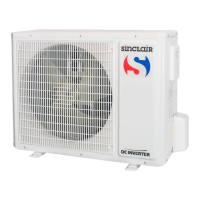
Lists models for outdoor units, including capacity, power supply, and appearance.
Details models for outdoor units, listing specifications like capacity, power supply, and refrigerant type.
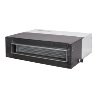
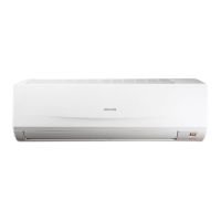
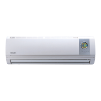
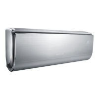
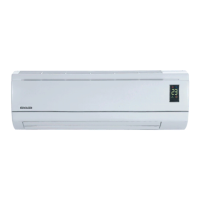
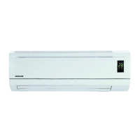
Details models for indoor units, covering type, capacity, power supply, and appearance.
Explains the coding system for classifying different unit types and their components.
Detailed specifications for units at rated conditions, covering various types like Duct, Ceiling, and Cassette.
Detailed specifications for duct-type indoor and outdoor units at rated conditions.
Detailed specifications for ceiling-type indoor and outdoor units at rated conditions.
Detailed specifications for cassette-type indoor and outdoor units at rated conditions.
Provides electrical specifications for various unit models, including power supply and fuse ratings.
Flowcharts illustrating the operational sequences for cooling/dry and heating modes.
Details the main logic and sequences for cooling, dry, heating, defrosting, and fan modes.
Details the main logic and sequence of operations for the cooling mode.
Describes the operational logic for the dry mode, highlighting differences from cooling mode.
Explains the main logic and sequence of operations for the heating mode.
Details the conditions for starting and ending the defrosting cycle.
Outlines the operational logic for the fan-only mode.
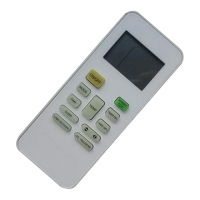
Illustrates the operational layout and buttons of the wireless remote controller.
Explains the icons and information displayed on the wireless remote controller's screen.
Shows the operational layout and buttons of the wired remote controller.
Details the display elements and their meanings on the wired remote controller.
Provides instructions and cautions for installing the wired remote controller.
Details the function and operation of centralized controllers without week timer functionality.
Explains the function and operation of centralized controllers with week timer capabilities.
Defines error codes displayed on the indoor wired controller and their corresponding malfunctions.
Provides detailed steps and precautions for installing indoor units, including duct, ceiling, and cassette types.
Covers pre-installation checks, site selection, and specific installation cautions for duct-type units.
Details installation procedures for ceiling-type units, including site selection and mounting precautions.
Outlines installation steps for cassette-type units, covering site selection and specific cautions.
Provides guidelines for selecting the installation site and performing the installation of outdoor units.
Details pre-installation checks and handling procedures for outdoor units.
Specifies criteria for selecting an appropriate installation site for outdoor units.
Details the procedures for connecting refrigerant pipes, including flaring, tightening, and vacuuming.
Explains general wiring principles, power supply requirements, and connection methods.
Presents field wiring diagrams for various indoor and outdoor unit combinations.
Lists error codes, their origins, and control descriptions for indoor wired controller faults.
Defines error codes displayed on the indoor wired controller and their corresponding malfunctions.
Troubleshooting flowcharts for various fault conditions and unit types.
Guides service personnel on collecting malfunction information and analyzing potential causes.
Troubleshooting steps for single-phase outdoor units, covering PFC and IPM module protection.
Troubleshooting steps for three-phase outdoor units, covering driver board and DC busbar protection.
Troubleshooting for 3-phase S series outdoor units, focusing on IPM protection and radiator overheat.
Troubleshooting for DC busbar overvoltage, checking input voltage and potential damage.
Troubleshooting steps for DC busbar undervoltage, checking input voltage and cable integrity.
Addresses troubleshooting for abnormal noise from the PFC inductor, involving moisture, dirt, and short circuits.
Guides troubleshooting for radiator overheat protection, checking radiation, dirt, and module tightening.
Troubleshooting steps for tripping issues, checking switches and module conditions.
Illustrates interface connections for various mainboards, referencing silkscreen labels.
Wiring diagrams for ASGE-18AI, ASGE-24AI, ASGE-36AI outdoor units.
Wiring diagrams for ASD and ASF series indoor units.
Exploded views and spare parts lists for various unit models.
Exploded view and spare parts list for the ASGE-18AI outdoor unit.
Exploded views and parts lists for ASD series duct indoor units.
Exploded views and parts lists for ASC series cassette indoor units.
Exploded views and parts lists for ASF series floor-ceiling indoor units.
| Brand | Sinclair |
|---|---|
| Model | ASGE-18AI |
| Category | Air Conditioner |
| Language | English |