DC INVERTER U-MATCH AIR CONDITION MAINTENANCE
105
2 FLOW CHART OF TROUBLESHOOTING
Troubleshooting sequence: Firstly, check the error code according to the wired controller fault display in
Table 1. If E5 is displayed, it is needed to open the electric box on outdoor unit and record the LED display
on the main board of outdoor unit. Then, refer to Table 3 - Main board Display Codes for Outdoor Unit and
find out the error. For 3-phase unit, it is also needed to record the LED display on the driver board of outdoor
unit. Then, refer to Table 3 - Main board Display Codes for Outdoor Unit and Table 4 - Driver Board Fault
Display Codes for 3-phase Unit, and find out the error. After determining the error, find out the reason
according to the instructions below.
Notes:
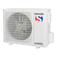
E5 is most special among all the fault codes displayed on wired controller. Both the external overload
protection of compressor and the main board fault of variable-frequency outdoor unit can cause the wired
controller to display E5. In the event of E5 error, firstly check the display codes on the main board of outdoor
unit and compare it with Table 3 - Main board LED indicators Display Codes for A series Outdoor Unit and
Table 5 - Main board dual 8 numeral tube Display Codes for B series Outdoor Unit. If the display is
“compressor overload protection (with A series outdoor unit, The LED6 ~ LED1 is respectively: bright, blink,
dark, blink, dark, dark and with B series outdoor unit, the dual 8 numeral tube display E5), please proceed as
described in “E5 Compressor Overheat” in 2.1 - System Troubleshooting below. Otherwise, please proceed
as described in 2.2 – Typical Troubleshooting for A series Outdoor Unit Drive (Inverter) by Single-phase
Motor, 2.3 – Typical Troubleshooting for A series Outdoor Unit Drive (Inverter) by Three-phase Motor, 2.4 –
Typical Troubleshooting for B series Outdoor Unit Drive (Inverter) by Single-phase Motor and 2.5 –Typical
Troubleshooting for B series Outdoor Unit Drive (Inverter) by Three-phase Motor .In the terms above, the
main board of variable-frequency outdoor unit includes but is not limited to the main control board and driver
board. In GUHD09NK3AO/ GUHD12NK3AO/ GUHD18NK3AO, the main control board and driver board of
the outdoor unit, together with other boards on the main board of variable-frequency outdoor unit, are
contained on one PCB board. Therefore, it looks more like one main board only.
2.1 System Troubleshooting
Service personnel shall collect the malfunction information as much as possible and research them
thoroughly, list these electrical parts which may cause malfunction, service personnel shall be able to
determine the specific reason and solve the faulted parts.
z Observe the status of the complete device and do not observe the partial
z It is advised to start from the simple operation during analyzing, judging and confirming malfunction
reason, then conduct the complicated operations such removal of device, part replacement and
refrigerant filling.
Find the malfunction reason carefully as unit may occur several malfunction at the same time and one
malfunction may develop into several malfunction, so entire system analysis shall be established to make
the judged result exact and credible.
 Loading...

