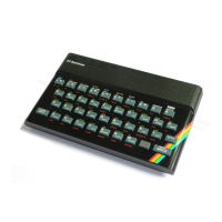
Do you have a question about the Sinclair ZX and is the answer not in the manual?
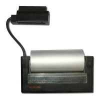
Provides context for the ZX Printer's purpose and capabilities.
Explains the unconventional two-styli printing mechanism and paper contact.
Lists the six main assemblies of the ZX Printer.
Details the components and attachment of the top cover assembly.
Describes the endless belt with attached styli and its pulley system.
Explains how the motor and gear train drive the belt, paper feed, and encoder disc.
Details the mounting and function of the control electronics board.
Describes the base frame and its removable insert for mounting components.
Explains the paper reel carrier assembly and pinch roller function.
Explains the function of the LED, photodiode, and encoder disc for signal timing.
Explains the function of TR1 and TR2 for the 50V power supply.
Covers vertical zig-zag, uneven spacing, fading, and noisy printing issues.
Addresses problems like all-black print, no image, or component defects.
Covers motor operation, speed, and inadequate paper feed problems.
Details procedures for cleaning dust and lubricating components.
Describes how to remove and install the top cover assembly.
Provides steps for removing and installing the belt and styli assembly.
Details the process for removing and installing the motor and gear train.
Outlines the procedure for removing and installing the PC board, loom, and edge connector.
Explains how to remove and install the encoder disc.
Details the steps for removing and installing the paper feed roller assembly.
Describes fitting the pinch roller springs for the paper reel carrier.