23
stud, being sure that the lug (M, Fig. 19) engages
the short recess (P) to prevent the plate from turn-
ing on the stud. Next, place the two tension discs
(H) on the stud, having the flat thread-bearing sides
of the discs together; then replace the indicator (G)
with the large open side facing end of stud so that
the plus and minus signs will be readily seen from a
sewing position as shown in Fig. 20. Insert the ten-
sion spring (F) in the indicator so that the first half
turn of this spring will straddle the lower half of the
tension stud. Guide the stop washer (D) onto the
stud so that the extension (S) will be above the
tension stud as shown_ in Fig. 20.
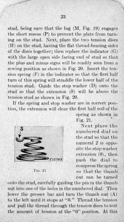
If the spring and stop washer are in correct posi-
tion, the extension will clear the first half coil of the
spring as shown in
Fig. 21.
Next place the
numbered dial on
the stud so that the
numeral 2 is oppo-
site the stop washer
extension (S), then
E 1 2 769
push the dial to
compress the spring
FIG. 21
so that the thumb
nut can be turned
onto the stud, carefully guiding the pin in the thumb
nut into one of the holes in the numbered dial. Then
lower the presser bar and turn the thumb nut (A)
to the left until it stops at "0." Thread the tension
and pull the thread through the tension discs to test
the amount of tension at the "0" position. At this
23
stud,
being sure that the lug (M, Fig. 19)
engages
the short recess (P) to prevent the plate from
turn-
ing
on the stud. Next, place the two tension discs
(H)
on the stud, having the fiat thread-bearing sides
of the discs together; then replace the indicator (G)
with
the large
open
side facing end of stud so that
the plus and minus signs
will
be readily seen from a
sewing position as shown in Fig. 20.
Insert
the ten-
sion spring (F) in the indicator so that the
first
half
turn
of this spring
will
straddle the lower
half
of the
tension stud. Guide the
stop
washer (D)
onto
the
stud
so that the extension (S)
will
be
above
the
tension stud as shown in Fig. 20.
If
the spring and
stop
washer are in correct posi-
tion,
the extension
will
clear the
first
half
coil of the
onto
the stud, carefully guiding the pin in the thumb
nut
into one of the holes in the numbered
dial.
Then
lower the presser bar and
turn
the thumb nut (A)
to the left
until
it
stops
at '^0." Thread the tension
and
pull
the thread through the tension discs to test
the amount of tension at the "0" position. At this
spring
as shown in
Fig.
21.
s
FIG.
21
Next
place the
numbered
dial
on
the stud so that the
numeral
2 is
oppo-
site
the
stop
washer
extension (S), then
push the
dial
to
compress
the spring
so that the thumb
nut
can be turned
 Loading...