From the library of Superior Sewing Machine & Supply LLC - www.supsew.com
SPECIFICATIONS
The following
gauge
distances should
be
of
help to
adjusters
of
these machines:
• Height
of
presser foot
above
throat
plate
5/16
inch.
• Distance from
throat
plate
seat
to
needle
stop
in
needle
bar
(needle
bar
at
lowest point),
1.004
inches.
•
Needle
bar
stroke
1.472
inches
• Rise
of
needle
bar
when point
of
shuttle
is
at
center
of
needle
(loop lift),
.100
inch.
VARIATIONS: Certain conditions of sewing
may
necessitate slight variations from these settings.
\
~---
EA~·
..........
--::y._
r::._
=_
-:c.~'~,
B .
0
D
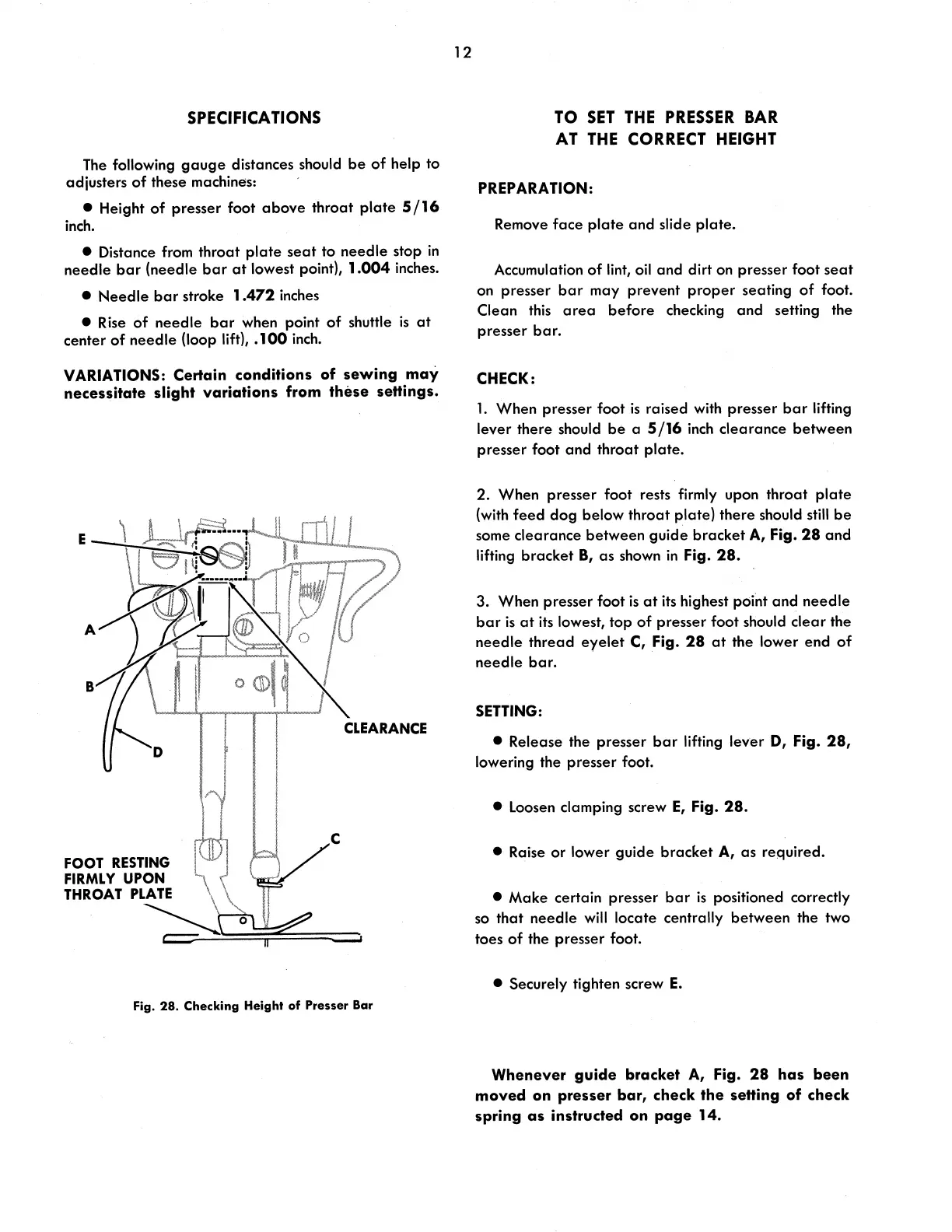
FOOT RESTING
FIRMLY
UPON
l,
THROAT
PLATE
\
~o
c::::-
CLEARANCE
C
Fig. 28. Checking Height
of
Presser Bar
12
TO
SET
THE
PRESSER
BAR
AT
THE
CORRECT
HEIGHT
PREPARATION:
Remove
face
plate
and
slide
plate.
Accumulation
of
lint, oil
and
dirt on presser foot
seat
on presser
bar
may
prevent
proper
seating
of
foot.
Clean this
area
before
checking
and
setting the
presser
bar.
CHECK:
1.
When
presser foot
is
raised with presser
bar
lifting
lever there should
be
a
5/16
inch
clearance
between
presser foot
and
throat
plate.
2.
When presser foot rests firmly upon
throat
plate
(with
feed
dog
below
throat
plate)
there
should
still
be
some
clearance
between
guide
bracket
A, Fig.
28
and
lifting
bracket
B,
as
shown
in
Fig.
28.
3. When presser foot
is
at
its highest poi'nt
and
needle
bar
is
at
its
lowest,
top
of
presser
foot should
clear
the
needle
thread
eyelet
C, Fig.
28
at
the lower
end
of
needle
bar.
SETTING:
• Release the presser
bar
lifting lever
D, Fig.
28,
lowering the presser foot.
• Loosen clamping screw
E,
Fig.
28.
• Raise
or
lower
guide
bracket
A,
as
required.
•
Make
certain presser
bar
is
positioned correctly
so
that
needle
will
locate centrally
between
the two
toes
of
the presser foot.
• Securely tighten screw
E.
Whenever guide bracket A, Fig.
28
has been
moved
on
presser bar, check the setting of check
spring as instructed on page 14.