From the library of Superior Sewing Machine & Supply LLC - www.supsew.com
TO
SET
THE
NEEDLE
BAR
AT
THE
CORRECT
HEIGHT
PREPARATION:
Remove
face
plate, slide
plate
and
throat plate.
See
that
needle
is
correctly
set
in
needle
bar,
as
instructed
on
page 5.
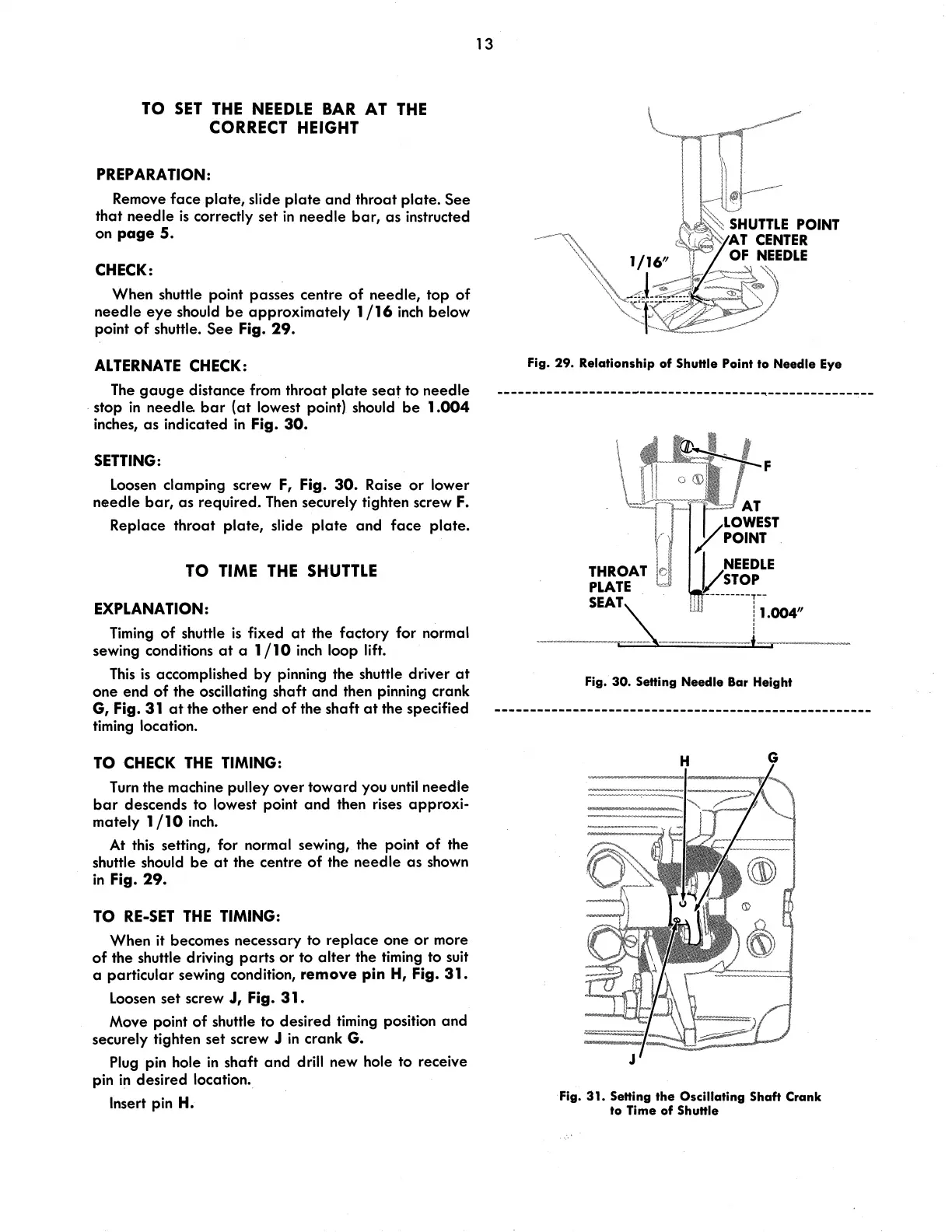
CHECK:
When shuttle point passes centre
of
needle,
top
of
needle
eye
should
be
approximately 1
/16
inch
below
point
of
shuttle.
See
Fig.
29.
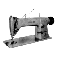
ALTERNATE CHECK:
The
gauge
distance from throat
plate
seat
to
needle
· stop
in
needle.
bar
(at
lowest point) should
be
1.004
inches,
as
indicated
in
Fig.
30.
SETTING:
Loosen clamping screw
F,
Fig.
30.
Raise
or
lower
needle
bar,
as
required. Then securely tighten screw
F.
Replace
throat
plate,
slide
plate
and
face
plate.
TO
TIME
THE
SHUTTLE
EXPLANATION:
Timing
of
shuttle
is
fixed
at
the factory for normal
sewing conditions
at
a 1
/10
inch
loop lift.
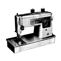
This
is
accomplished
by
pinning the shuttle driver
at
one end
of
the oscillating shaft and then pinning crank
G,
Fig.
31
at
the other end
of
the shaft
at
the specified
timing location.
TO
CHECK
THE
TIMING:
Turn
the machine pulley
over
toward you
until
needle
bar
descends to lowest point
and
then rises
approxi-
mately 1 / 10
inch.
At
this setting, for normal sewing, the point
of
the
shuttle should
be
at
the centre
of
the needle
as
shown
in
Fig.
29.
TO
RE-SET
THE
TIMING:
When it becomes necessary to
replace
one
or
more
of
the shuttle driving
parts
or
to
alter
the timing to suit
a particular sewing condition,
remove pin H, Fig. 31.
Loosen
set
screw
J,
Fig. 31.
Move point
of
shuttle to desired timing position
and
securely tighten
set
screw J
in
crank G.
Plug pin hole
in
shaft
and
drill new hole to receive
pin
in
desired location.
Insert pin
H.
13
Fig. 29. Relationship of Shuttle Point
to
Needle
Eye
-------------------------------------~------------
.--
THROAT e
PLATE
sa~\
F
---------T-.
I 1.004"
I
l
Fig. 30.
Setting
Needle Bar Height
Fig. 31. Setting the Oscillating Shaft Crank
to
Time of Shuttle