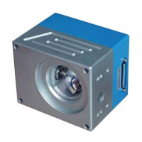
The SINO-GALVO Model SG7310 Galvanometer Scanner is a high-performance optical scanning system designed for various laser applications. Developed by SINO-GALVO (BEIJING) TECHNOLOGY CO., LTD., a high-tech enterprise specializing in optical scanning galvanometers, this device incorporates advanced international photoelectric sensor technology and PDM control mode, utilizing military-grade processes and technologies to ensure reliability and precision.
Function Description:
The SG7310 Galvanometer Scanner is primarily used for directing laser beams with high accuracy and speed. It is a core component in laser precision engraving, laser cutting, laser welding, rapid prototyping, drilling positioning, medical cosmetology, scientific research, and military fields. The system's design focuses on achieving stable operation, high positioning accuracy, and fast marking speeds, while also offering strong anti-interference capabilities.
Important Technical Specifications:
The SG7310 system comprises motors and a servo drive board, each with specific technical parameters:
Motor Specification:
- Working Temperature: 0-45°C
- Linearity: 99.9%
- Setting Time: ≤0.35ms
- Scale Drift: <40PPM/°C
- Zero Drift: <15µRad./°C
- Long-term Drift Over 8 Hours: <0.5mRad
- RMS Current: 2.0A
- Peak Current: 15A (Max)
- Maximum Scan Angle: ±15°
- Storage Temperature: -10 to +60°C
- Resolution: 12µrad
- Repeatability: 8µrad
- Input Aperture: 10.0mm
- Beam Displacement: 13.4mm
- Motor Weight: 120g
- Frequency: ≤1000Hz
Servo Drive Board Specification:
- Input Voltage: ±15VDC
- Interface Signals:
- Digital: XY2-100
- Analog: ±5V, ±10V
- Position Signal Input Resistance: 1KΩ±1%
- Position Signal Input Scale Factor: 0.33V/°
- Position Signal Output Scale Factor: 0.33V/°
- Working Temperature: 0-45°C
- Dimension (L×W×H): 75×50×28mm
The scanner housing dimensions are approximately 96.5mm (width) x 118.5mm (height) x 94mm (depth), with specific mounting points and an M79x1 thread. The motor dimensions are approximately 31mm (diameter) x 71.2mm (height) or 81.2mm (height) depending on the variant, with a 22mm diameter base.
Usage Features:
The SG7310 scanner system offers several key usage features:
- High Precision and Stability: It utilizes photoelectric sensors imported from America, ensuring accurate detection of motor rotor position, good linearity, low drift, high resolution, and excellent repeat positioning.
- Optimized Design: Accurate load design for 10mm mirrors, high accuracy of motor assembly, reasonable structure, very small static friction coefficient, and zero offset contribute to optimal dynamic characteristics.
- Enhanced Dynamic Response: Drives with advanced position and speed detection capabilities significantly improve dynamic response performance and scanning speed.
- Robust Protection: The system incorporates overload, over-current, and reverse connect protection, enhancing operational reliability.
- Electromagnetic Compatibility: Optimized electromagnetic compatibility design results in a high signal-to-noise ratio and strong anti-interference ability.
- Problem Solving: The system effectively addresses common issues such as motor temperature drift, signal interference, and zero drift.
Wiring and Connection:
The system requires careful wiring for both power supply and signal connections.
- Power Supply: The power supply unit connects to AC220V (L and N) and provides ±15VDC (GND, -15V, GND, GND, +15V) to the drive boards.
- DB25 Connection: The DB25 connector handles both digital (XY2-100) and analog (±5V, ±10V) interface signals. Specific pins are assigned for CLOCK+, CLOCK-, SYNC+, SYNC-, CHAN1+, CHAN1-, CHAN2+, CHAN2-, +15V, -15V, and GND. For analog wiring, pins are assigned for X+, X-(GND), Y+, Y-(GND), +15V, -15V, and GND. It is crucial to follow the wiring diagrams precisely to avoid damage or malfunction.
Maintenance Features (Self-checking and Troubleshooting):
Before operation, a thorough self-check is recommended:
- Pre-startup Check: Verify all connections, especially the DB25 wiring, to ensure no virtual connections, disconnections, or incorrect sequences. Confirm that mirrors are not touching each other and drive board signal inputs are correct.
- Troubleshooting Guide:
- System no reactions: Check if the power supply is connected correctly and if the circuit is properly wired.
- Scan motor swings lightly after turning on: Investigate potential interference sources and the input signal circuit.
- Motor screams, drive board/motor overheat: Check wiring, and inspect mirrors and clips for proper installation.
- Mirror reflection power is weak: Adjust the light path of the marking machine. If the issue persists, contact technical support.
- Marking figures become one straight line: Check the wiring connection between motors, drive boards, and the control board, as this indicates one motor is not moving normally.
- Waves exist in the marking line: Check ground connection, identify strong interference sources, and assess the anti-interference ability and position control signal of the marking control board.
Special Notices:
- Wiring Sequence: Always ensure the DB25 wiring sequence on the scanner housing is correct before starting the marking system to prevent malfunction or damage.
- Motor/Drive Board Matching: Motors and drive boards must be connected according to their corresponding serial numbers and are not interchangeable. Mismatching can lead to self-excitation.
- Laser Light Path Accuracy: Verify the accuracy of the laser light path output. Inaccurate paths can affect marking accuracy, cause displacement, and lead to non-uniform laser intensity.
For any questions or technical assistance, customers can contact SINO-GALVO (BEIJING) TECHNOLOGY CO., LTD. via their service consulting hotline or through their provided contact information.