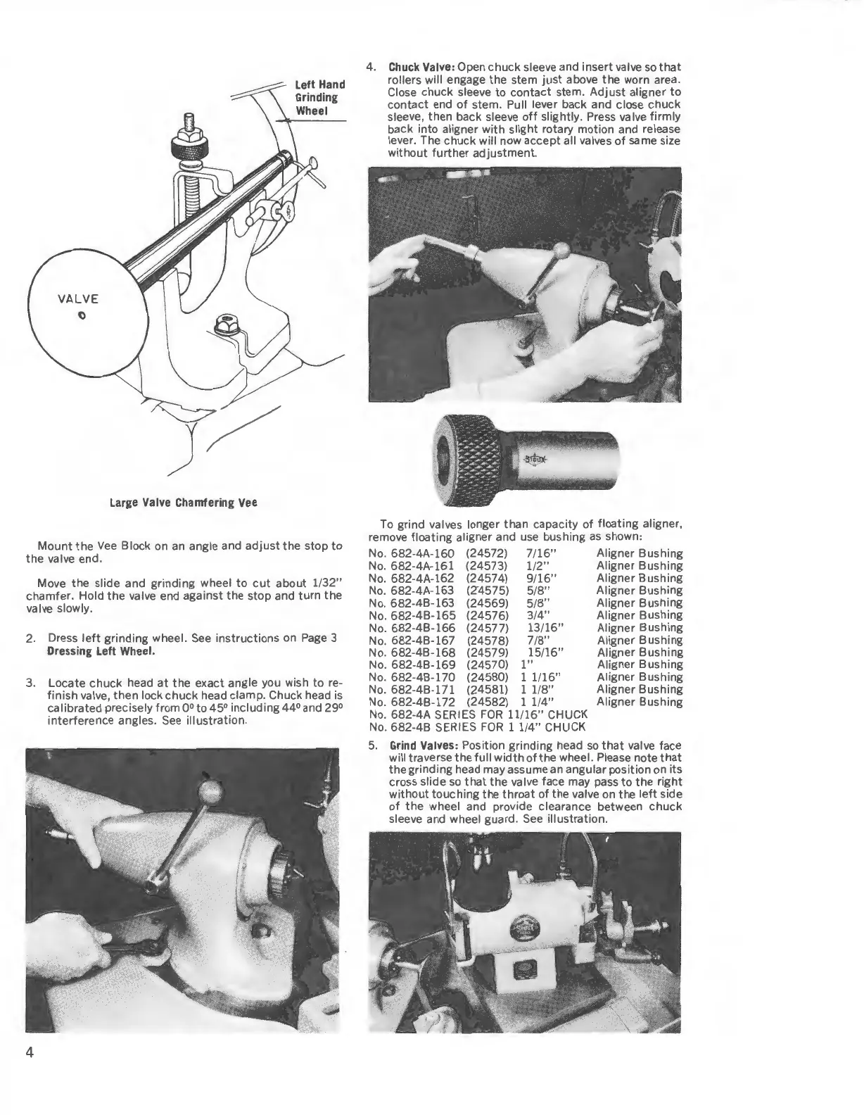
Large
Valve
Chamfering
Vee
Left
Hand
Grinding
Wheel
Mount
the
Vee
Block on
an
angle and
adjust
the stop
to
the valve end.
Move the slide and grinding wheel to
cut
about 1/
32"
chamfer. Hold the valve end against the stop and
turn
the
valve slowly.
2. Dress
left
grinding wheel.
See
instructions
on
Page
3
Dressing
Left
Wheel.
3.
Locate chuck head
at
the exact angle you wish to re-
finish valve, then lock chuck head clamp. Chuck head is
calibrated precisely from 0° to 45° including 44° and 29°
interference angles.
See
illustration.
4
4.
Chuck
Valve:
Open chuck sleeve and insert valve
so
that
rollers will engage the stem
just
above the worn area.
Close chuck sleeve
to
contact stem. Adjust aligner
to
contact end
of
stem. Pull lever back and close chuck
sleeve, then back sleeve
off
slightly. Press valve firmly
back into aligner
with
slight rotary motion and release
lever. The chuck will now accept all valves of same size
without
further
adjustment.
To
grind valves longer than capacity of floating aligner,
remove floating aligner and use bushing
as
shown:
No. 682-4A-160 (24572) 7/
16"
Aligner Bushing
No.
682-4A-161 (24573)
1/2"
Aligner Bushing
No.
682-4A-162 (24574)
9/16"
Aligner Bushing
No
. 682-4A-163 (Z4575) 5/8" Aligner Bushing
No
. 682-4B-163 (24569) 5/
8"
Aligner Bushing
No. 682-4B-165 (24576) 3/4" Aligner Bushing
No
. 682-4B-166 (24577)
13/16"
Aligner Bushing
No.
682-4B-167 (24578) 7/
8"
Aligner Bushing
No.
682-4B-168 (24579) 15/
16"
Aligner Bushing
No.
682-4B-169 (24570)
1"
Aligner Bushing
No. 682-4B-170 (24580) 1 1/
16"
Aligner Bushing
No
. 682-4B-171 (24581) 1 1/
8"
Aligner Bushing
No. 682-4B-172 (24582) 1
1/4"
Aligner Bushing
No. 682-4A SERIES
FOR
11
/
16"
CHUCK
No.
682-4B SERIES
FOR
1 1/
4"
CHUCK
5.
Grind
Valves:
Position grinding head
so
that
valve face
will traverse the full
width
of the wheel. Please note
that
the grinding head
may
assume
an
angular position on its
cross slide
so
that
the valve face may pass
to
the
right
without touching the throat of the valve on the
left
side
of
the wheel and provide clearance between
chuck
sleeve and wheel guard.
See
illustration.
 Loading...