1/12/2011 3 SIP 2000 instructions revised B
The various input and output connections for the SIP 2000 are conveniently located on the bottom of the main
control unit. For operation, insert the female end of power cord A into the male Plug A (shown in diagram above with
a red “in” label) The opposite end of Plug A will fit a standard wall outlet but should not be plugged into a power
supply until the SIP 2000 has been completely installed in the water dispenser.
Insert power cord B into the female socket B (shown above with a green “out” label). Plug the main power supply
cord for the water dispenser into the female or opposite end of cord B.
The air pump is the small rectangular box found in the SIP 2000 box. The air pump power supply cord is
permanently attached to the air pump and cannot be removed, this must be fitted to the SIP 2000 box in the area
marked DC12v position in the diagram.
The optional led display light system can be connected in the area shown in the diagram. The function of these lights
is described below. A multi-colored ribbon cable with a led light on one end and a 6-pronged connector on the
opposite end has been packed with your unit.
The SIP 2000 is protected by a 2 amp fuse located near the left side of the power cord B socket. The fuse is clearly
marked “fuse”.
A green “go” button and wire connector is included with your SIP 200 unit. This device allows the programming to be
overridden for short test periods in order to verify that the SIP unit is working properly. The male end of the “go”
button wire should be inserted into the female “go” button socket located on the bottom of the SIP main control unit.
The green button can then be attached in a discreet location onto the exterior of the cooler. Once inserted the “go”
button will activate the O
3
operation whenever the green button is depressed.
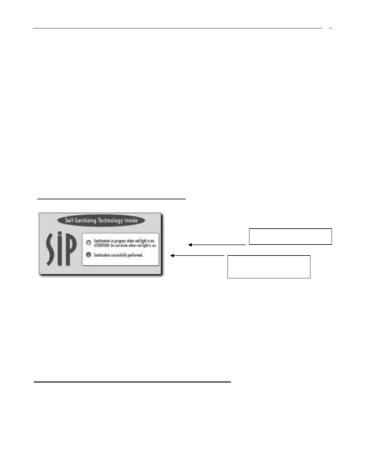
External Indicator Lights of SIP2000
The external indicator light is only used to display the working status of the various functions when the SIP2000 machine
is in normal operation. This optional led feature can be fitted to the front of the water cooler and mounted on the label
provided.
The red light is the O
3
indictor and will illuminate when O
3
is in operation.
The green light is the power indicator which will turn on when a power supply is connected. It will go out when power is
not connected.
Red Light indicates O
3
is in operation
Green Light indicates O
3
treatment
has been successfully performed and
cooler has resumed normal operation.
 Loading...