EasyManua.ls Logo

Sirio Antenne New Vector 4000 User Manual

Sirio Antenne New Vector 4000
2 pages
To Next Page IconTo Next Page
Page #1 background imageLoading...
Page #1 background image
20
B Copyright SIRIO antenne - Technical Data are subjected to change - Printed in ITALY - Rev. 06/03/2009 - Cod. ID041, pag. 4/4
HI-QUALITY ANTENNAS MADE IN ITALY
MOUNTING INSTRUCTIONSMOUNTING INSTRUCTIONS
19
14
13
1
0
mm
17
Insert the top section with
the cage (21) at L3 (see
tuning table for
frequency) and lock it
using the M4x4 hexagon
socket set screw cup
point (22) and 2mm
hexagonal key (23).
Pull out the 5 sections of
telescopic aluminium
whip (24) and lock them
using the 3.9x9.5mm
phillips tapping screws
(25).
Æ
Insert the fully assembled
telescopic whip into the
second section of tube
(10) and lock they using
the 3.9x9.5mm phillips
tapping screws (25).
Æ
5
4
3
20
L3
22
23
25
24
24
10
28
7
8
26
9
27
21
25
25
24
19
77
88
99
1010
1111
1212
UHF female connector
Finally mount the
antenna on the mast
using M6 washer (7), M6
spring lock washer (8),
M6 hexagonal nut (9),
steel bracket (26 & 27)
and M6x240mm U-bolt
(28).
Insert the aluminium tube
10x1400 (19) into the
assembled cone tubes
13x1400 (17). Pull out the
top tube for 1310 mm and lock
it using the 3.9x12.7mm
phillips tapping screws (14).
Æ
Æ
Æ
Mount the 4 pcs of the
aluminum ring (20) and
lock them using M5x16
hexagon head screw (3),
M5 washer (4) and M5
hexagonal nut (5).
HI-QUALITY ANTENNAS MADE IN ITALY
ID041, pag.1/4
NEW VECTOR 4000NEW VECTOR 4000
27...28.5 MHz CB & 10m band Base Station Antenna
3/4 l Base station antenna working on CB and 10m band.
Made of telescopic anti-corodal aluminium tubes. Its long and
robust whip allows perfect performances and very good
connections at long distances too.
DESCRIPTIONDESCRIPTION
SPECIFICATIONSSPECIFICATIONS
TECHNICAL DATA
Electrical Data
Type
Frequency range
Impedance
Radiation ( H-plane)
Polarization
Gain
Bandwidth @ SWR £ 2)
SWR @ res. freq.
Max Power
Feed system
Connector
Mechanical Data
Materials
Wind resistance
Length (approx.)
Weigth (approx.)
Mounting Mast
: 3/4 l Coaxial J-pole
: 27...28.5 MHz tunable
: 50 W
: 360° omnidirectional
: Vertical
: 2 dBd, 4.15 dBi
: ³ 1400 KHz (120 channel)
: £ 1.2
: 1000 Watts continuous
3000 Watts short time
: Gamma match
: UHF-female
: Aluminium, Steel, Brass, Nylon
: 130 Km/h
: 8480 mm
: 4700 gr
: Æ 35-42 mm
Question and Answer IconNeed help?

Do you have a question about the Sirio Antenne New Vector 4000 and is the answer not in the manual?

Sirio Antenne New Vector 4000 Specifications

General IconGeneral
Radiation PatternOmnidirectional
Impedance50 Ohms
PolarizationVertical
SWR at Resonance< 1.2:1
MountingMast
Max Power1000 Watts

Summary

Mounting Instructions

Step 7: Insert Aluminium Tube

Insert the aluminium tube 10x1400 (19) into assembled cone tubes 13x1400 (17).

Step 8: Mount Aluminium Ring

Mount the 4 pcs of the aluminum ring (20) and lock them using M5x16 screws, M5 washer, and M5 hexagonal nut.

Step 9: Pull Out Telescopic Whip

Pull out the 5 sections of telescopic aluminium whip (24) and lock them using 3.9x9.5mm phillips tapping screws (25).

Step 10: Insert Top Section

Insert the top section with the cage (21) at L3 and lock using M4x4 set screw and 2mm hexagonal key.

Step 11: Mount Plastic Ring

Mount the plastic ring (12) on the second aluminium tube (10) at 1340 mm and lock with arms (13) and screws (14).

Step 12: Mount Antenna on Mast

Mount the antenna on the mast using M6 washer, spring lock washer, M6 hexagonal nut, and U-bolt (28).

Product Description

Technical Specifications

Electrical Data

Details on antenna type, frequency range, impedance, radiation, polarization, gain, bandwidth, SWR, and power.

Mechanical Data

Information on materials, wind resistance, length, weight, and mounting mast diameter.

Typical SWR Response

Tuning Table and Remarks

Tuning Table

Table showing length adjustments (L1, L2, L3) for different frequencies (MHz).

Remark and Needed Tools

Advice on using SWR-Meter, cable, mounting location, and a list of required tools.

Parts List

Detailed Mounting Instructions

Step 1: Mount Aluminium Bracket

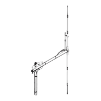
Mount bracket (1) at distance L1 from bottom ring, aligning bracket and connector. Lock with screws, washer, nut.

Step 2: Mount Gamma Match

Mount the gamma match (6) on the connector and lock it using M6 washer, spring lock washer, and M6 hexagonal nut.

Step 3: Adjust Gamma Match

Pull out aluminium bar of gamma match at distance L2 from plastic cap and lock with bracket, screw, washer, nut.

Step 4: Insert Second Section

Insert second section of aluminium tube (10) into first section tube (2) and lock with enclosed hose clamp (11).

Step 5: Mount Cone

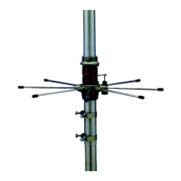
Mount the cone made of aluminium tubes 13x1400 (17) on the bottom aluminium ring using M6x12 screws, washer, and lock washers.

Step 6: Insert Limit Punching

This step is indicated with text 'Insert limit punching' next to step 5 diagram.

Related product manuals