Do you have a question about the Sirona DAC PROFESSIONAL and is the answer not in the manual?
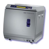
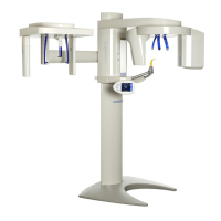
Details the various components and connections of the DAC Professional unit.
Specifies the necessary clearance and environmental conditions for unit setup.
Covers power supply, wastewater outlet, and demineralized water supply requirements.
Form for recording installation details, customer information, and warranty registration.
Defines the required maintenance intervals: every 2nd year or 2000 cycles.
Important checks and safety instructions to be followed before commencing maintenance.
Instructions for handling service records after maintenance is completed.
Safety precautions for performing service work on the unit.
Ensuring the autoclave is correctly positioned and slopes to the rear for proper drainage.
Checking the internal chamber and tray rack for dirt or rust.
Inspecting the door gasket for damage and cleaning if necessary.
Checking door hinges for play and securing retaining rings of hinge bolts.
Checking and adjusting the door contact switch for proper door closure detection.
Disassembling and cleaning the cooler, fan, and cooler ribs.
Procedures for exchanging the sterile filter and cleaning pressure-release filters.
Verifying tightness of cables and power-conducting tab connectors.
Checking all internal hoses for damage and correct positioning.
Performing and evaluating the vacuum test program for leak rate and pump performance.
Carrying out a fast program test with unwrapped objects and checking for leakages.
Instructions for resetting the maintenance counter as per separate instructions.
Confirming the successful completion of maintenance and signing the service record.
Section for attaching print-outs from Vacuum-Test and Quick-Program.
Schematic of component groups, pipes, and hoses in the vacuum unit.
Conditions that trigger the vacuum system fault monitoring.
Actions for operating staff and technical personnel to correct vacuum system problems.
Flowchart for diagnosing and correcting vacuum system faults.
Checking control system and vacuum pump function for performance issues.
Troubleshooting weak vacuum performance due to solenoid valves or intake line resistance.
Procedures for checking leaks in various solenoid valves within the vacuum system.
Methods for searching leaks at screwed and bonded connections using soap solution.
Monitoring time limits exceeded for warming-up and heating phases of the steam generator.
Covers operating faults and appliance faults for the steam generator.
Monitoring time limit exceeded for pressure release until reaching P11.
Addresses issues like solenoid valve not opening, clogged filter, and sensor readings.
Monitoring time limit exceeded for chamber ventilation until reaching pressure P12.
Covers dirty sterile filter, ventilation valve issues, and sensor signal faults.
Excessive difference between program cycle duration and CPU clock time.
Operator checks for disturbances and technical correction for hardware defects.
Door contact not switching correctly during a program.
Procedure for adjusting the door contact switch for proper door closure detection.
Capillary tube controller open or monitoring time Uet18 exceeded.
Addresses faults like cold start issues, faulty capillary control, or output ACOUT1 issues.
Diagnosing issues with the feed pump, solenoid valve, and water level control.
Door locking contact DIN5 not switching after time period z31.
Procedures for adjusting the door lock and troubleshooting when it fails to disengage.
Flow sensor or float switch detecting a shortage of demineralized water.
Addresses issues with water supply systems, float switches, and flow sensors.
Checking water-treatment systems and suction from water-storage tanks.
Ensuring sufficient water in the internal tank and free movement of the float switch.
Checking activation control for feed-water pump and valve.
Verifying float switch function and signal processing on the main circuit board.
Testing the feed-water dosing unit's supply volume and feed rate.
Checking signal processing and adjusting the flow sensor.
Description of sensors and their corresponding analog inputs used in the system.
Large deviations in temperature, pressure, or conductivity sensor readings.
Troubleshooting temperature sensor faults and signal processing issues.
Diagnosing faults related to pressure sensors and conductivity sensors.
Monitoring time limit exceeded for preheating until reaching the necessary temperature.
Addresses low mains voltage, cold appliance, and faulty preheating control.
Preheating temperature limit exceeded.
Checks for faulty pre-heating output or sensor signal processing.
Maximum permissible deviation in CPU signal processing (A/D-conversion) exceeded.
Correction involves exchanging the CPU-board for hardware signal processing faults.
Deviation between two temperature sensors exceeds permissible limit.
Troubleshooting based on print-out values to identify faulty sensor or signal processing.
Data inconsistency or loss in CPU memory due to electrical disturbance or low battery.
Correcting time/date settings or exchanging the battery/CPU board.
Evacuation pressure exceeded maximum permitted value during vacuum test.
Examining door seal and checking solenoid valves for leaks.
Searching for leaks at screwed and bonded connections, and filter stoppers.
Loss of power supply after program start, with reminder to sterilize filter.
Checks for faulty power switch, fuses, internal wiring, or CPU board power supply.
Maximum operating time to reach operating pressure exceeded.
Addresses security valve leaking and vacuum solenoid valve leaking.
Temperature fell below minimum level for sterilization/disinfection.
Checks for no saturated steam, sensor issues, or signal processing faults.
Troubleshooting high pressure sensor readings and steam generator response issues.
Flowchart for diagnosing sterilization TU faults based on print-out readings.
Measured pressure indicates temperature above maximum limit.
Checks for faulty temperature sensors, pressure sensors, or steam generator output.
Flowchart for diagnosing sterilization TO faults based on print-out readings.
Calculated temperature for saturated steam is below minimum temperatures.
Addresses pressure drops, overheating protection trips, and sensor signal fluctuations.
Measured pressure indicates temperature above maximum limit.
Checks for faulty steam generator output, pressure sensor fluctuations, or poor heat transition.
Maximum difference between calculated and measured temperature exceeded.
Addresses no saturated steam, sensor issues, and pressure sensor measurement errors.
Stored parameters do not guarantee a successful sterilization cycle.
Checking and correcting sterilization cycle parameters in the service program.
Common operator errors leading to poor drying performance.
Identifying autoclave issues like insufficient vacuum or blocked components.
Explanation of the information contained in the cycle log print-out.
Analysis of temperature and pressure graphs during sterilization cycles.
Table correlating temperature and absolute pressure of saturated steam.
Using the spiral unit and indicator strip for steam penetration testing.
Criteria for evaluating satisfactory steam penetration based on indicator strip color change.
Steps for performing the Bowie & Dick test to check air removal and steam penetration.
Interpreting test results based on uniform color change of the indicator.
Schematic representation of valves and their functions within the autoclave system.
Flowchart and button guide for accessing various diagnostic functions.
Overview of parameters accessible through the Service Program for configuration.
Records changes made to the manual, including revision number, date, and description.
| Brand | Sirona |
|---|---|
| Model | DAC PROFESSIONAL |
| Category | Laboratory Equipment |
| Language | English |