EN 60584
EN 60584
DIN 43710
EN 60584
EN 60584
EN 60584
EN 60584
EN 60584
EN 60584
EN 60751
EN 60751
°C
°F
-199.9...600.0
-30.0....600.0°C
-30.0....600.0°C
-30.0...999.9°C
-30.0...400.0°C
-200...600
-30....600°C
-30....600°C
-30...1300°C
-30....400°C
-40...1700°C
-40...1700°C
°C
°C
-22.0....999.9 °F
-22.0....999.9 °F
-22.0....999.9 °F
-22.0....752.0 °F
-199.9...999.9
-22....2372 °F
-22......752
-40....3092
-40....3092
-328....1112
-22....1112 °F
-22....1112 °F
°F
°F
°F
°F
°F
EUPx420-EN-01-181112
SİSEL MÜHENDİSLİK ELEKTRONİK SAN. VE TİC. A.Ş.
Şerifali Mah. Y.Dudullu 34775
ÜMRANİYE/İSTANBUL-TURKEY
Tel : +90 216 499 46 64 Pbx. Fax : +90 216 365 74 01
url : www.enda.com.tr
Barbaros Cad. No:18
1/6
Order Code : EUP
1
1 - Size
4420.....48x48x87mm
7420.....72x72x97mm
8420.....48x96x87mm
9420.....96x96x50mm
2 -
230VAC...90 - 250V AC
SM...........9-30V DC /
7-24V AC
Supply Voltage
3 -
RS........ RS-485
Blank....
Modbus (Optional)
Modbus Available
(Optional / Specify at order).
N/A
2
0
2 3
4
DIN 43710
ENDA
TM
ENDA EUP SERIES PID UNIVERSAL CONTROLLER
Thank you for choosing ENDA EUP Series Universal Controller Devices.
Pl
ea
se
r
ea
d th
is
do
c
um
e
nt
ca
r
e
f
u
l
ly b
ef
or
e
us
ing
t
hi
s
p
r
o
d
uc
t.
Th
e
gu
a
ra
nt
ee
w
ill
be
i
nv
al
i
da
t
e
d
i
f
t
he
d
e
vice
i
s
dam
a
g
e
d
by
n
o
t
f
o
l
l
o
w
in
g
i
n
st
r
uc
ti
o
n
s
d
e
t
ailed
i
n
t
he
m
a
n
u
a
l.
T
h
e
c
o
mpa
n
y
sh
all not
be
r
e
s
po
n
si
b
le
fo
r
a
n
y
d
a
mag
e
o
r l
o
sse
s
h
o
we
v
er
c
a
us
e
d,
whi
c
h
m
ay
b
e
e
xp
e
rienc
ed
a
s
a
r
esu
lt
o
f
t
h
e
i
n
s
t
allatio
n
or
us
e
of
th
i
s
pr
od
uct.
Dual setpoint value can be selected.
PT100 ,J, K, L, T, S, R sensor (thermocouple) types can be selected.
0-20mA, 4-20mA, 0-10V, 2-10V, 0-25mV and 0-50mV input selections.
Auto calculation for PID parameters (SELF TUNE).
Three different feature can be assigned to digital input.
Three different feature can be assigned to F function key.
Soft-Start feature.
Analogue, SSR or Relay Output Control selection.
0-20mA and 4-20mA Analogue Output Control selection.
Up to 16 steps Profile Control.
A1 Relay output programmable as first Alarm or Cooling control output.
C/A2 Relay output can be used as second Alarm or Temperature Control output.
Heating/Cooling control selection.
Zero point input shift.
In case of sensor failure, periodically, auto-periodically running or relay state can be selected.
RS485 Modbus RTU communication protocol feature (Specify at order).
CE marked according to European Norms.
Self tune for automatic PID calculation or
manually enter PID parameters if known.
Input Type
Scale Range
J (Fe-CuNi) Thermocouple
L (Fe-CuNi) Thermocouple
J (Fe-CuNi) Thermocouple
L (Fe-CuNi) Thermocouple
K (NiCr-Ni) Thermocouple
K (NiCr-Ni) Thermocouple
T (Cu-CuNi) Thermocouple
T (Cu-CuNi) Thermocouple
S (Pt10Rh-Pt) Thermocouple
R (Pt13Rh-Pt) Thermocouple
PT100 Resistance Thermometer
PT100 Resistance Thermometer
0-20mA input
0-10V input
2-10V input
0-25mV input
0-50mV input
4-20mA input
-1999...+9999 (max. scale range 10000)
-1999...+9999 (max. scale range 10000)
-1999...+9999 (max. scale range 10000)
-1999...+9999 (max. scale range 10000)
-1999...+9999 (max. scale range 10000)
-1999...+9999 (max. scale range 10000)
0,5% (for full scale)
0,5% (for full scale)
0,5% (for full scale)
0,5% (for full scale)
0,5% (for full scale)
0,5% (for full scale)
1 digit
1 digit
1 digit
1 digit
1 digit
1 digit
0,5% (for full scale)
0,5% (for full scale)
1 digit
1 digit
0,5% (for full scale) 1 digit
0,5% (for full scale) 1 digit
0,2% ( )for full scale
1 digit
0,2% ( )for full scale 1 digit
0,2% ( )for full scale
0,2% ( )for full scale
0,2% ( )for full scale
0,2% ( )for full scale
0,2% ( )for full scale
0,2% ( )for full scale
1 digit
1 digit
1 digit
1 digit
1 digit
1 digit
Accuracy
ENVIRONMENTAL CONDITIONS
Height
Ambient/storage temperature
Max. Relative humidity
Rated pollution degree
ELECTRICAL CHARACTERISTICS
Supply
Power consumption
Wiring
Line resistance
Data retention
EMC
Safety requirements
OUTPUTS
A1 Output
Life expectancy for relay
C/A2 Output
ANL/SSR Output
CONTROL
Control type
Control algorithm
A/D converter
Sampling time
Proportional band
Control period
Hysteresis
Output power
HOUSING
Housing type
Dimensions
Weight
Enclosure material
90-250V AC, 50/60Hz or 9-30VDC / 7-24VAC ±%10 SMPS
Max. 5VA
Power screw-terminal connections: 2.5mm²', Signal screw-terminal connections: 1,5mm².
EN 61326-1: 2013 (Performance criterion B satisfied for EN 61000-4-3 standard).
EEPROM (minimum 10 years)
Max. 100 Ohm
EN 61010-1: 2010 (Pollution degree 2, overvoltage category II)
Suitable for flush-panel mounting according to DIN 43 700.
EUP4420 : W48xH48xD87mm, EUP7420 : W72xH72xD97mm,
EUP8420 : W48xH96xD87mm, EUP9420 : W96xH96xD50mm.
Approx. 400g (250g for EUP4400) After packing.
Self extinguishing plastics
Single Setpoint and Alarm Control.
On-Off / P, PI, PD, PID (selection).
14 bit.
Min. 100ms.
Can be adjusted between %0.0 and %100.0 . If Pb=%0.0 , ON-OFF control is selected.
Can be adjusted between 1 and 125secs.
Can be adjusted between 1 and 50°C/F.
Setpoint value ratio can be adjusted between %0 and %100 .
Relay : 250V AC, 8A (for resistive load), NO+NC (Control or Alarm2 Output selection).
Relay : 250V AC, 8A (for resistive load), NO (Alarm1 and Cooling Control Output selection).
Max. 2000m
0 ... +50°C/-25 ... +70°C
According to EN 60529; Front panel : IP65, Rear panel : IP20
Max. SSR Output ; 0-20mA, 4-20mA, 24V 20mA. Max. load resistance ; 600 Ohm (12 bit 0.2% accuracy).
Relative humidity 80% for temperatures up to 31°C decreasing linearly to 50% relative humidity at 40°C.
Without load 30.000.000 switching; 250V AC, 8A (resistive load) 300.000 switching.
KEEP AWAY device from exposed to corrosive, volatile and flammable gases or liquids and DO NOT USE the device in similar hazardous locations.
Avoid any liquid contact when the device is switched on.
DO NOT clean the device with solvent (thinner, gasoline, acid etc.) and / or abrasive cleaning agents.
Please see EUPx420 Series Modbus
Address Map and Connection Diagram
Guide for Modbus feature.
UNIVERSAL CONTROLLER
ENDA
EUP7420
C/A2
SSR
A1
PV
SV
F
C/A SET
SET
A1 DEL.
A2 INS.
START
STOP
UNIVERSAL CONTROLLER
ENDA
C/A SET
F
SET
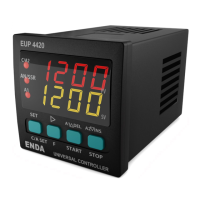
EUP4420
C/A2
A1
SSR
PV
SV
1200
1200
START
STOP
A1 DEL.
A2 INS.
A1
C/A2
SSR
UNIVERSAL CONTROLLER
EUP9420
ENDA
PV
SV
SET
F
C/A SET
START
STOP
A1 DEL.
A2 INS.
EUP8420
ENDA
UNIVERSAL CONTROLLER
SET
C/A SET
F
C/A2
SSR
A1
PV
SV
START
STOP
A1 DEL.
A2 INS.