Thermostat bulb
INSTALLATION
Main gas connection
The connection is made using gas pipes with NPT 1/2, 3/8 or 1/4 threading.
Water connection
The connection flange threading is NPT 3/4.
Connection to the pilot burner
Pipes with 1/4” diameter can be used.
Use a nut and olive of appropriate dimensions. Tighten 60 in. lbs. torque.
SETTINGS AND ADJUSTMENTS
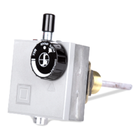
Setting the thermostat
The thermostat is set and sealed in the factory (A).
To provide user selection of 104 to 158 °F.
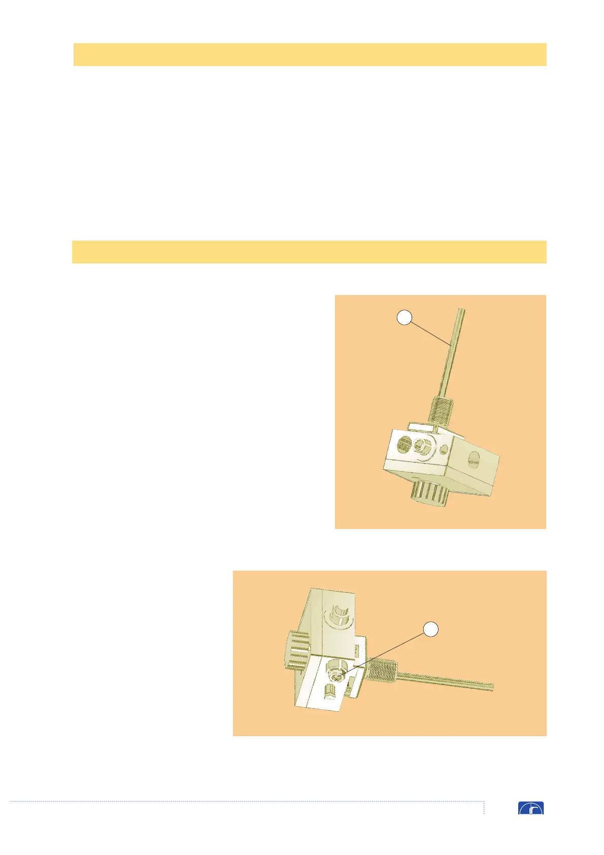
Adjusting the flow rate
Screw in the screw (B) to reduce the flow or
unscrew it to increase flow.
IMPORTANT
At the end of all setting and adjustment opera-
tions, check gas tightness and that the appliance
is operating properly.
Flow rate adjustment
B
A