650 DELTA USE AND INSTALLATION INSTRUCTIONS
3
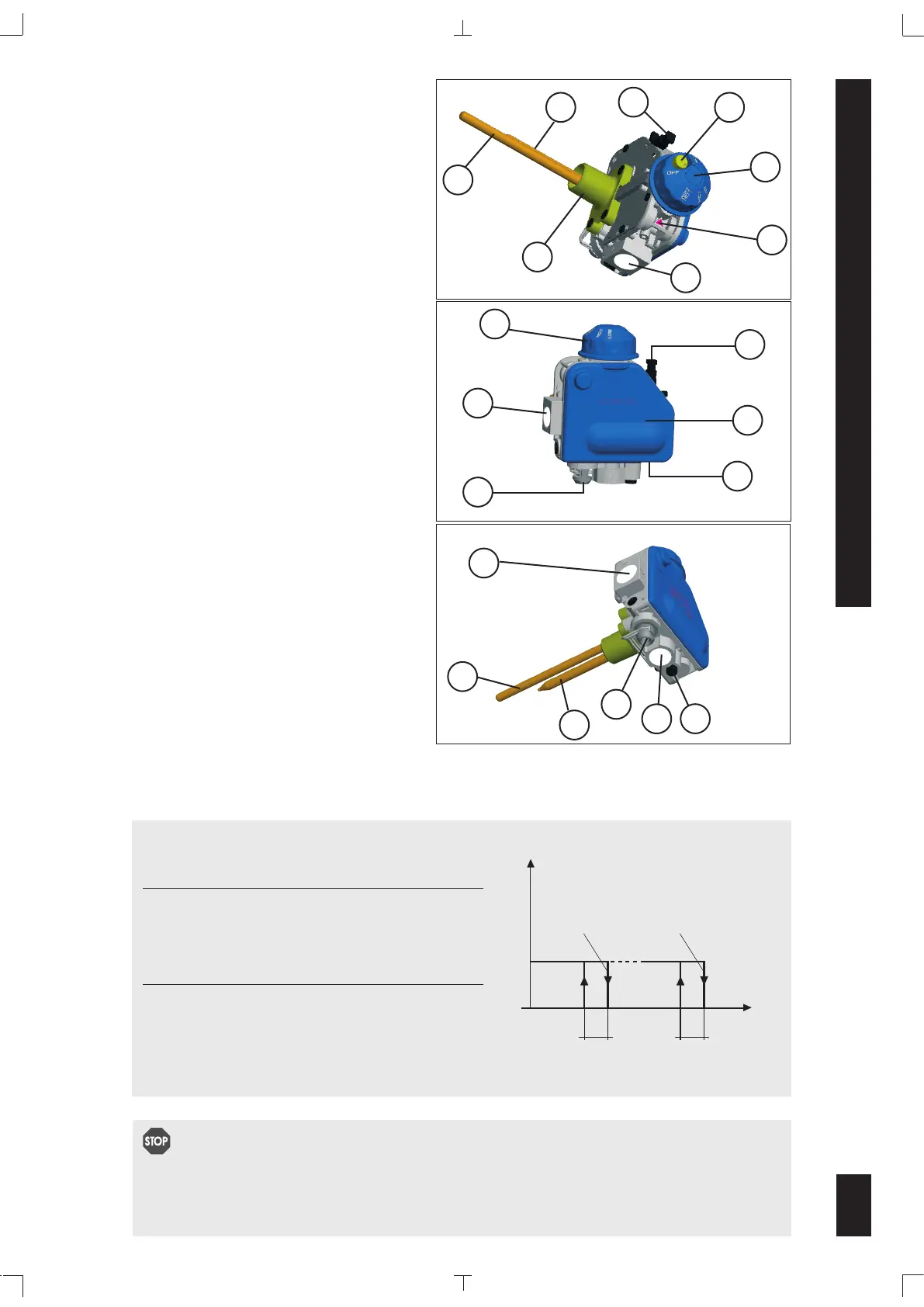
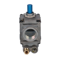
VALVE DESCRIPTION
1 Ignition button for thermoelectric flame
supervision device
2 Control knob
3 Reference arrow mark
4 Gas inlet with protective dust cap
5 Main gas outlet with protective dust
cap
6 Pilot outlet
8 Outlet pressure test point
9 Thermocouple connection
10 Mounting flange
11 Thermostat Rod
12 ECO Well
13 Piezoelectric igniter (Optional)
14 Plastic cover (Optional)
10
2
11
8
5
9
THERMOSTAT REGULATION SPECIFICATIONS
Thermostat Features
•
Regulating thermostat
Differential (a) 16 +/-5.5 °F
•
ECO
Type one-shot
Calibration 196 +0/-9 °F
TEMPERATURE
a
GAS FLOW
a
A B
MIN position MAX position
control knob at
control knob at
STOP
Do not install, replace, or in any way modify the gas valve or the appliance. Always
use a QUALIFIED Gas Appliance Service Technician to service appliances this valve is
installed on. ALWAYS READ AND FOLLOW ALL THE ENCLOSED INTRUCTIONS.
12
4
14
2
4
13
9
6
13
3
1
4
11
12