650 DELTA USE AND INSTALLATION INSTRUCTIONS
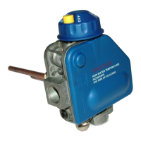
INSTALLING THE VALVE
1. Install the valve using the provided mounting flange.
Screw using using the specific tool SIT code 0.999.996,
suitable as accessory. Tighten to 45 ÷ 60 ft·bs torque.
2. Mount the valve so the flow of gas is consistent with
the gas flow arrows on the valve.
3. A p p l y a m o d e r a t e a m o u n t o f q u a l i t y
pi p ecompound to the pipe only, leaving two end
threads bare. On LP i
nstallations, use compound
that resists exposure to LP gas.
4. Remove seals over inlet and outlet if necessary.
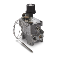
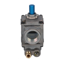
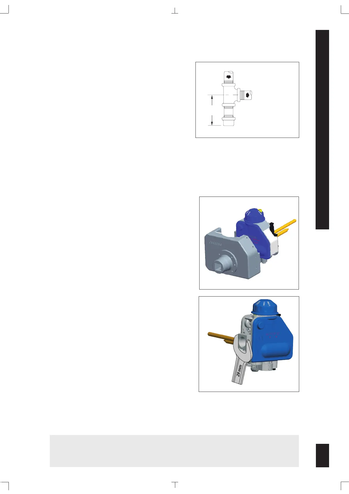
5. Connect pipe to valve inlet and outlet. Place wrench on
valve in position
(see Fig. 2). Tighten inlet connection
to 30 ft
·
lbs torque, outlet connection to 20 +/-10 ft
·
lbs
torque.
6. Thread pipe into the valve until a gas tight seal is
achieved. Typically, for NPT thread, penetration is
usually no more than the diameter of the pipe or 2
and 1/4 turns thread. Valve distortion or mechanical
failure can result if the pipe is inserted too deeply.
7. Connect pilot tubing to valve with appropriately
sized fittings. Recommended torque 40 ÷ 70 lbf·in.
8. Confirm gas tight seals with gas leak test.
9. Connect thermocouple to safety magnet. Hand tighten, and then rotate 1/4 turn with wrench
appling a torque not higher than 10 ÷ 20 lbf·in.
5
INSTALL PIPING TO GAS VALVE
All piping must comply with local codes and ordinances or with the National Fuel Gas code (ANSI
Z223.1 NFPA No. 54) whichever applies. Tubing installation must comply with approved standards
and practices. Use appropriately sized fittings when
connecting aluminum tubing to the pilot outlet.
1. Use new, clean and correctly reamed pipe free from
burrs, chips, debris and any foreign matter. When
tubing is used, make sure the ends are square
and clean. All tubing bends must be smooth and
without deformation.
2. Run pipe or tubing to the valve. If tubing is used,
obtain a tube-to-pipe coupling to connect the tubing to the valve.
3. Install sediment trap (Drip Leg) in the supply line to the gas valve.
3” MIN.
GAS SUPPLY
TO CONTROL
INLET
DRIP LEG (DOWN)
WARNING!
Do not immerse in water or subject the control to temperatures exeeding 175 °F
operating ambient temperature..
Fig. 2
Fig. 1
 Loading...