Shantou Institute of Ultrasonic Instruments Co., Ltd.
3
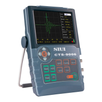
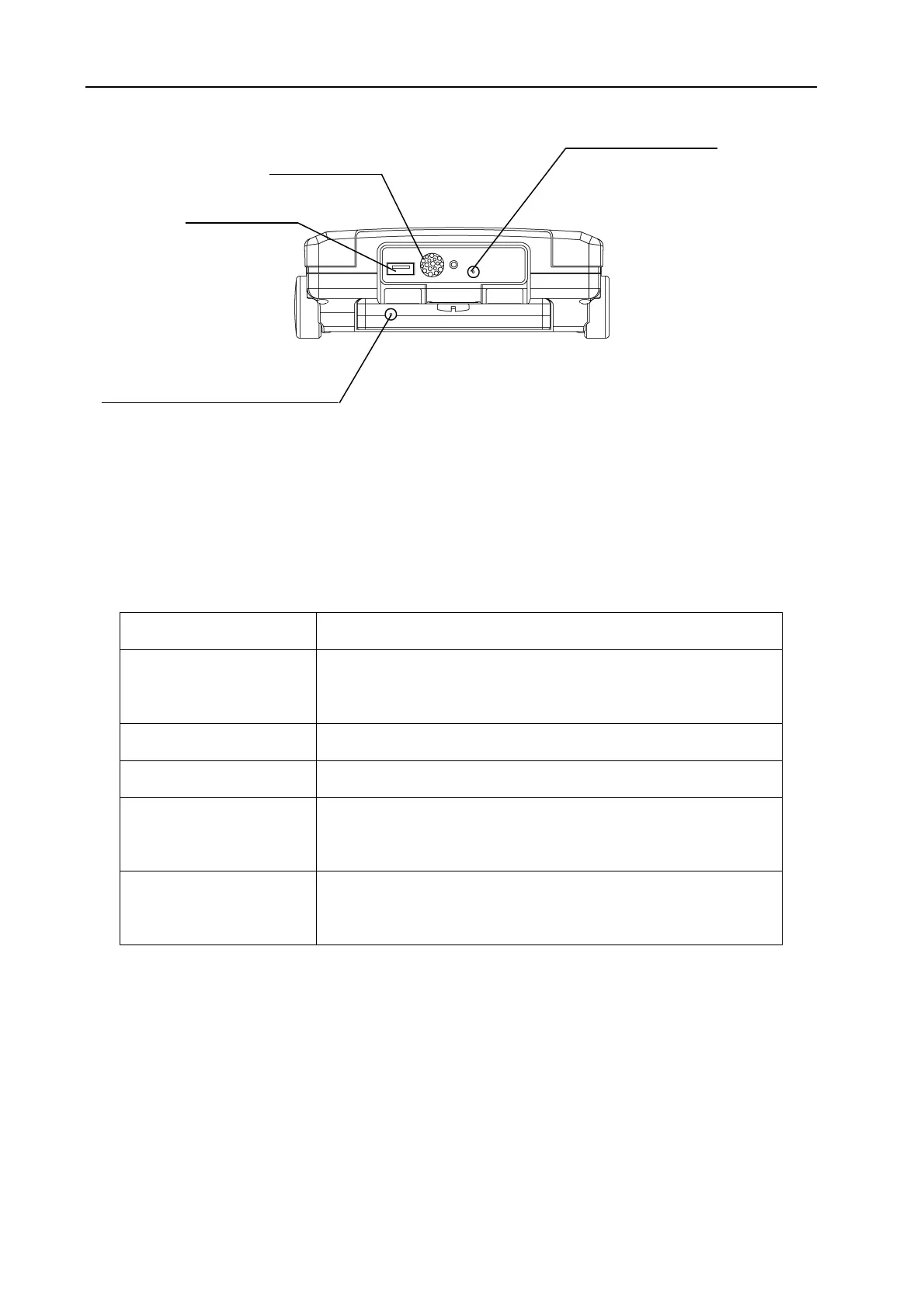
Fig. 1-4 System Top View
1.3 Port and Socket
Please refer to Fig. 1-3 and Fig. 1-4.
Table 1-1 Usage of Ports and Sockets
Name Usage
Probe Socket T, R
To connect a probe. T is for transmitting while R is for
receiving.
Buzzer Port The buzzer sound outlet when the alarm sound is enabled.
USB Port To connect a USB disk or a printer.
DC Power In Socket
For main unit power supply when connected to the external
charger/adaptor (CD-92).
Battery Charging In
Socket
For charging battery when connected to the external
charger/adaptor (CD-92).
1.4 Key
Please refer to Fig. 1-1 for key diagram and Table 1-2 for key functions.
DC Power In Socket
Buzzer Port
USB Port
Battery Charge In Socket
 Loading...