Quick Setup/Installation Guide for Lubrication Monitor Controller LMC 301
951-150-029-EN
6
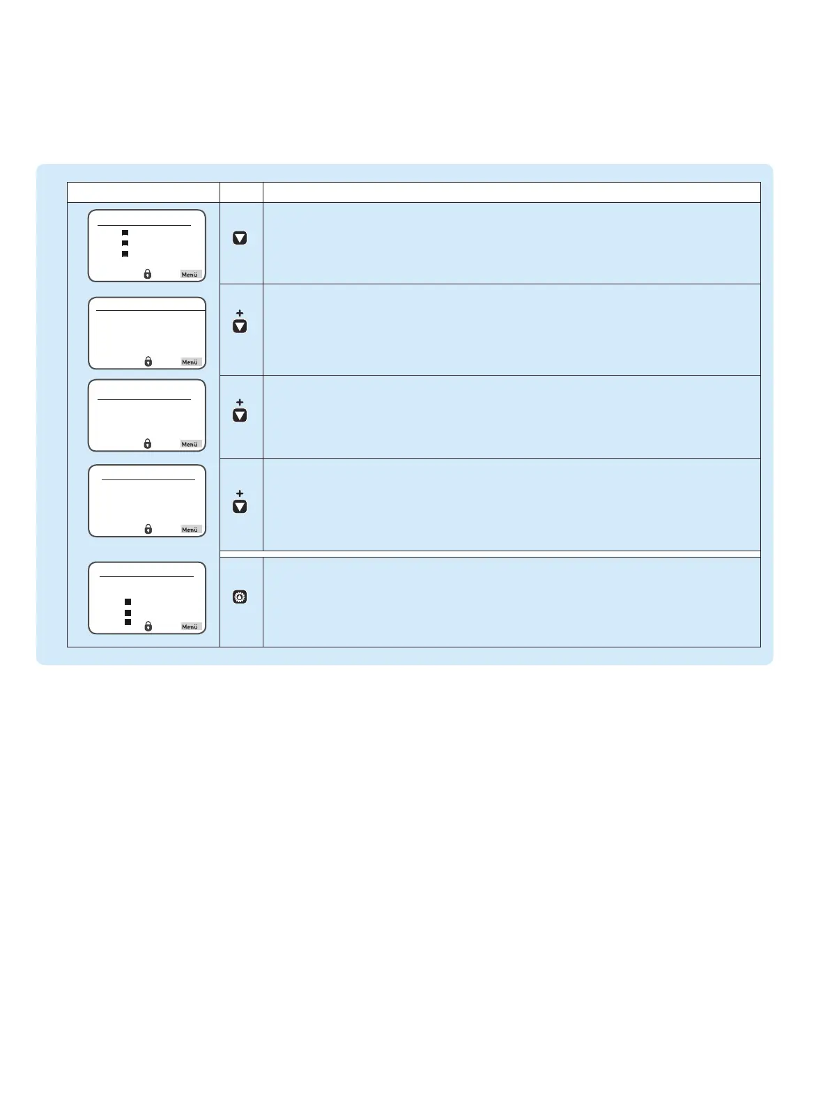
Status Overview and triggering an additional lubrication
Symbol Status Function
Press the arrow key to receive a status overview of the pumps resp. zones
(P1Z1 = Pump 1/Zone1 to max. P3Z3 Pump 3/Zone 3).
Press the arrow key again to display the residual pause time resp. residual runtime of the currently
selected pump/zone (e. g. P1Z1).
Press the arrow key again to display the activated inlets of the currently selected pump/zone.
Press the arrow key again to display the activated outlets of the currently selected pump/zone.
Press the "additional lubrication" key shortly to carry out an additional lubrication of the entire system
respectively of the activated zones (P1Z1 = pump 1/zone1 to max. max. P3Z3 pump 3/zone 3).
Overview States
P1Z1
P1Z2
P1Z3

 Loading...

