Align the shaft in the bearing arrange-6
ment axially and, if possible, turn it a few
times.
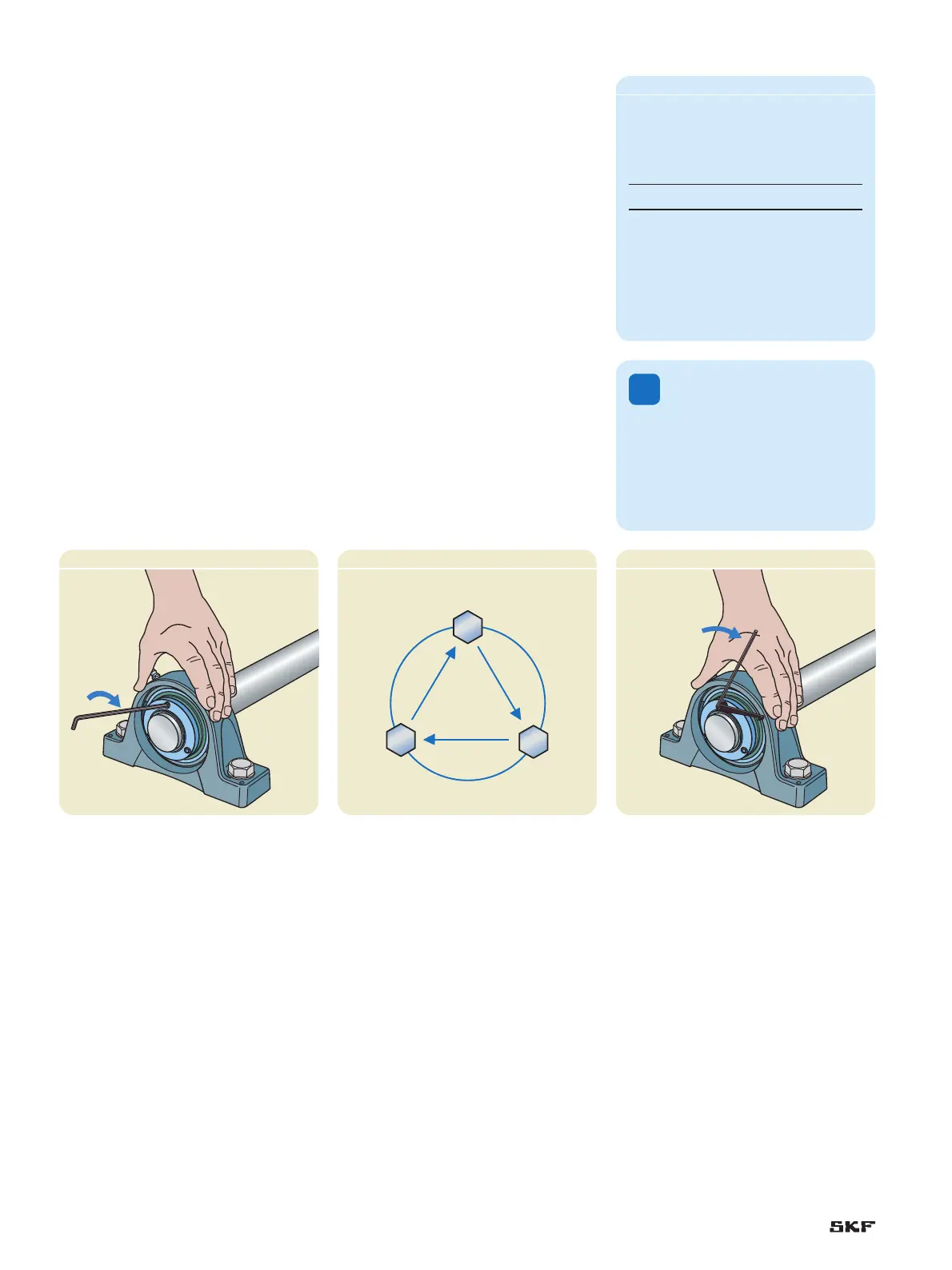
Start to secure the first bearing unit to 7
the shaft by positioning the collar so that
a grub screw is directly opposite the split
in the sleeve. Tighten the screws finger-
tight, holding the short leg of the supplied
hexagonal key († fig. 4).
Tighten the screws 1/4 turn following the 8
tightening pattern in fig. 5. Do this twice.
Then tighten each set screw, starting with
the screw opposite the split in the sleeve,
until the long end of the hexagonal key
comes in contact with the supplied torque
indicator († fig. 6) or to the recom-
mended torque value shown in table 2.
Dismounting instructions
Table 2
Recommended tightening torque values
Bearing size
1)
Screw
size
Recommended
torque
from to high
–
Nm / in.lbf
05 06 M5 4,2 / 37
07 13 M6 7,4 / 66
1)
For example: bearing size 07 includes all bearings based
on a Y 207 e.g. YSP 207 SB-2F, YSP 207-104 SB-2F,
YSP 207-106 SB-2F, YSP 207-107 SB-2F
!
Caution: Do not use auxiliary
equipment such as a hammer or
pipe to tighten the screws.
Secure the second bearing unit to the 9
shaft following steps 7 and 8. Make
sure the shaft turns smoothly and the
bearings are not jammed. If the shaft
does not turn smoothly, loosen one
of the bearing units following the
dismounting instructions and secure
it again.
If applicable, snap the end cover in 10
place.
Loosen and remove the attachment bolts 4
and slide the unit off the shaft.
Repeat the 5 steps 1 to 4 for the second
unit.
It may be necessary to clean the shaft ex-1
tension with emery cloth to remove rust
or repair surface damage.
Loosen the screws on the first unit.2
Lightly tap the sleeve edge on the mount-3
ing collar side of the bearing until the
locking system releases the shaft. As an
alternative, tap on the bearing inner ring
side face on the side opposite the collar.
Fig. 5
Fig. 6
18
 Loading...