EasyManua.ls Logo

SKF TMEA 2 - Page 23

SKF TMEA 2
35 pages
Print Icon
To Next Page IconTo Next Page
To Previous Page IconTo Previous Page
Loading...
24
S
h
a
f
t
a
l
i
g
n
m
e
n
t
t
o
o
l
S
K
F
T
M
E
A
2
3
.
8
A
l
i
g
n
m
e
n
t
r
e
s
u
l
t
s
3
.
8
.
1
M
e
a
s
u
r
e
d
misalignment
After the second measurement at
3
o'clo
ck ha
s been c
onfirmed
, the
misalignment of the two machines
in the measurement plane, the
plane where the measuring units
are (i.e. horizontal in this case) is
displ
ay
ed
(fig.
19).
Coupling values
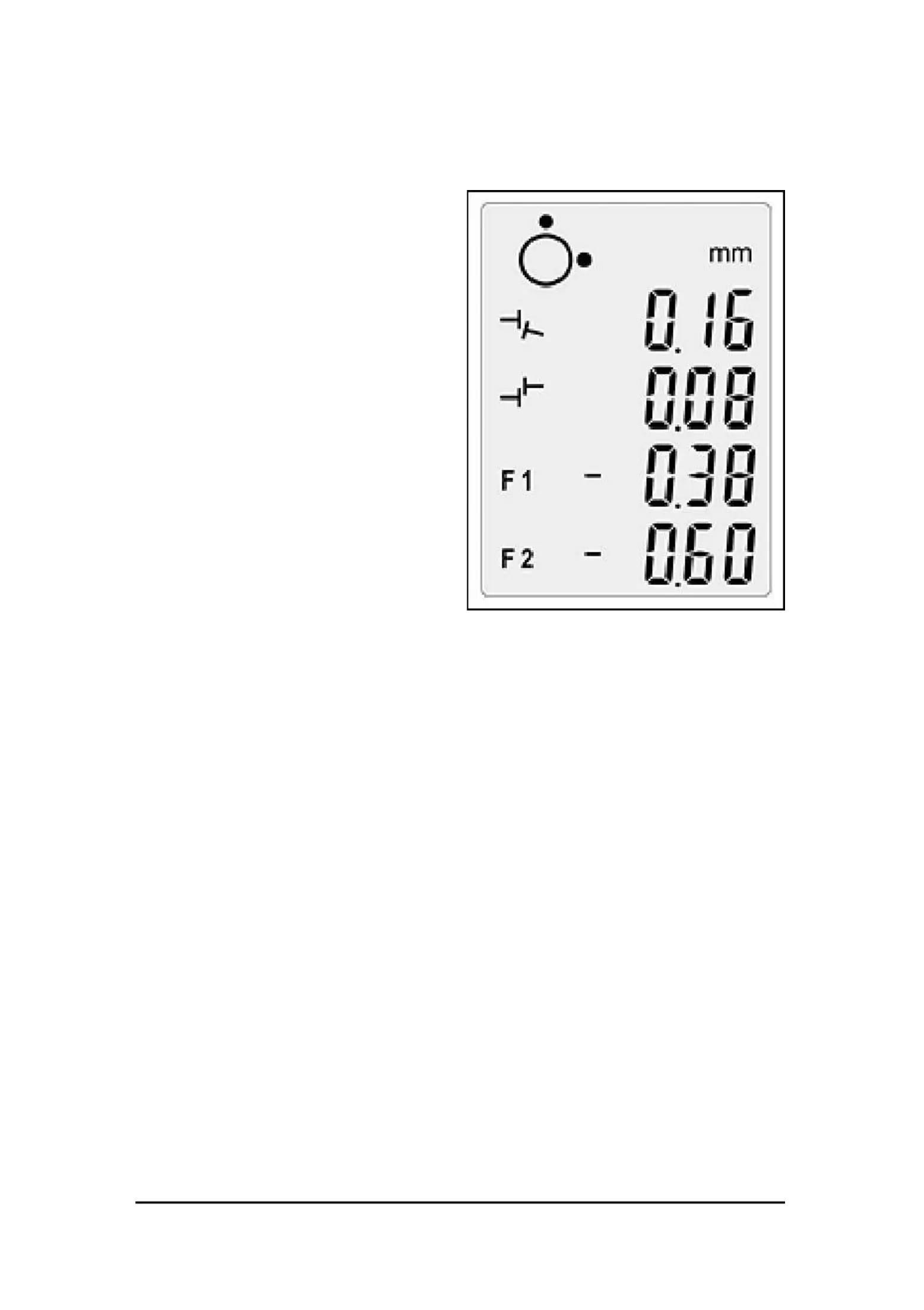
The coupling value on top of the
display shows the angle
between
the centre lines of the two shafts
in the measurement plane
(measured in mm/100 mm or
0.001"/1").
The value below on the
display
shows the parallel off-set of the
two centre lines in the
measurement plane.
These two values are the coupling
values in the measurement plane.
Feet values
The values F1 and F2 on the
display indicate the relativ
e positions of
the Movab
le machine in
the measurement plane.
The F1 value indicates the relative position of the front pair of feet of
the Movable machine.
The F2 value indicates the relative position of the rear pair of feet of
the Movable machine.
Fig.
19.
Meas
ured
misa
lign
ment

Related product manuals