EasyManua.ls Logo

SKF TMEA 2 - Alignment Verification

SKF TMEA 2
35 pages
Print Icon
To Next Page IconTo Next Page
To Previous Page IconTo Previous Page
Loading...
28
S
h
a
f
t
a
l
i
g
n
m
e
n
t
t
o
o
l
S
K
F
T
M
E
A
2
The F1 and F
2 values indicated
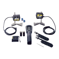
on the display give the relative
positions of the
Movab
le machine
when vie
wed fro
m abov
e (fig.
25).
The F1 value for the front pair of
feet, the F2 value is for the rear
pair of feet.
The alignment values indicate the
necessary corrective sideways
movement of the Movable
machine (when viewed from
behind the
Movab
le machine).
A negative value means that the
feet have to be mov
ed to the right
.
A positive value means that the
feet have to be moved to the left
(f
ig
.
26
).
Observe the coupling and
feet
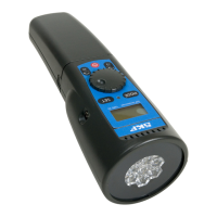
values live adjustment while
moving the movable machine
sideways.
The alignment is complete.
Tighten the feet of the movable
machine.
3
.
9
V
e
r
i
f
y
a
l
i
g
n
m
e
n
t
To verify the alignment of the machinery, it is recommended to
execute the measuring procedure once again. To do so, go back by
using the previous button until you reach the first
measuring step
(9
o'cloc
k pos
ition
) and c
ontin
ue as
per ch
apter
3.7.
Fig
. 25.
Dis
pla
y horiz
ont
al
alignment
Fig.
26.
Horiz
onta
l
alig
nment

Related product manuals