Section 04 ENGINE
Sub-Section 05 (CDI SYSTEM)
04-05-4
1. Magneto harness through crankcase hole
– Install new trigger coil and other parts re-
moved.
Adjustment
Whenever the trigger coil or the magneto fly-
wheel is removed or replaced, the air-gap be-
tween the trigger coil and the flywheel protrusion
must be checked and adjusted. The purpose of
this adjustment is to obtain the minimum clear-
ance between these parts – without touching at
any RPM – so that the trigger coil produces its
proper electrical output. Ignition timing must also
be checked. Refer to IGNITION TIMING 06-02
then look for Checking Ignition Timing.
CAUTION : Each time trigger coil air-gap
is adjusted, ignition timing must be
checked.
Proceed as follows :
1. Rotate flywheel so that the protrusion aligns
with trigger coil.
2. Using a feeler gauge of 0.75 mm (.030 in) min.
0.55 mm (.022 in) and max. 1.45 mm (.057 in)
thick, check air-gap between center pole of trig-
ger coil and flywheel protrusion.
3.If necessary, adjust by slackening retaining
screws and moving trigger coil toward or away
of protrusion.
4. Retighten screws and recheck air-gap.
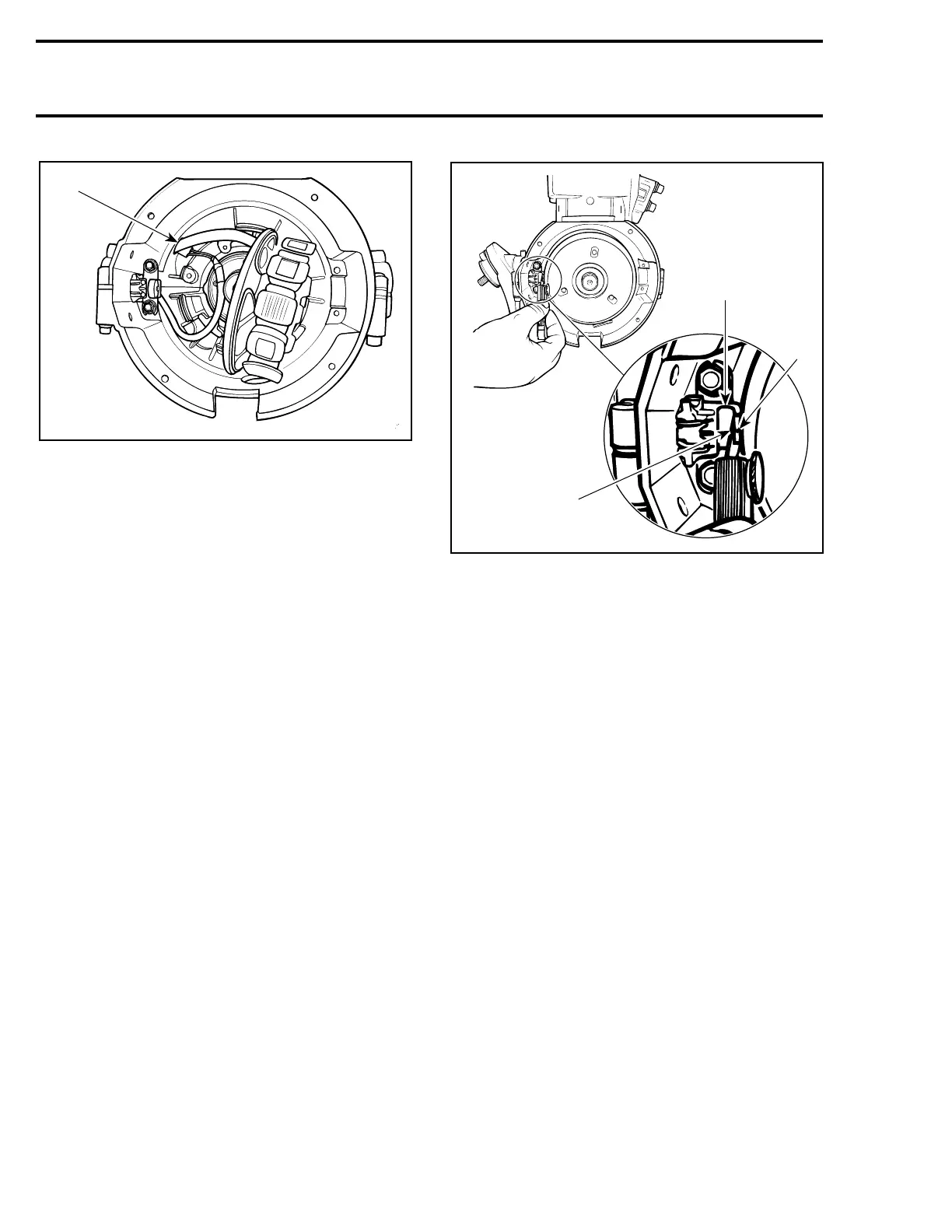
ADJUSTING TRIGGER COIL AIR-GAP
1. Trigger coil
2. Flywheel protrusion
3. Measure at center pole of trigger coil 0.75 mm (.030 in)
1, Stator
To replace stator :
– Disconnect the 3-wire connector (BLACK, RED
and BLACK / RED wires).
– Disconnect both YELLOW wires.
– Remove grommet from crankcase where mag-
neto harness exits magneto housing.
– Remove stator plate retaining screws.
– Remove stator plate with stator and carefully
pull wires.
– Install new parts and other parts removed tak-
ing care not to squeeze trigger coil harness.
A25E1AA
1
A15E0NA
2
3
1
 Loading...
