Section 06 ELECTRICAL
Sub-Section 06 (TESTING PROCEDURE)
06-06-2
➁
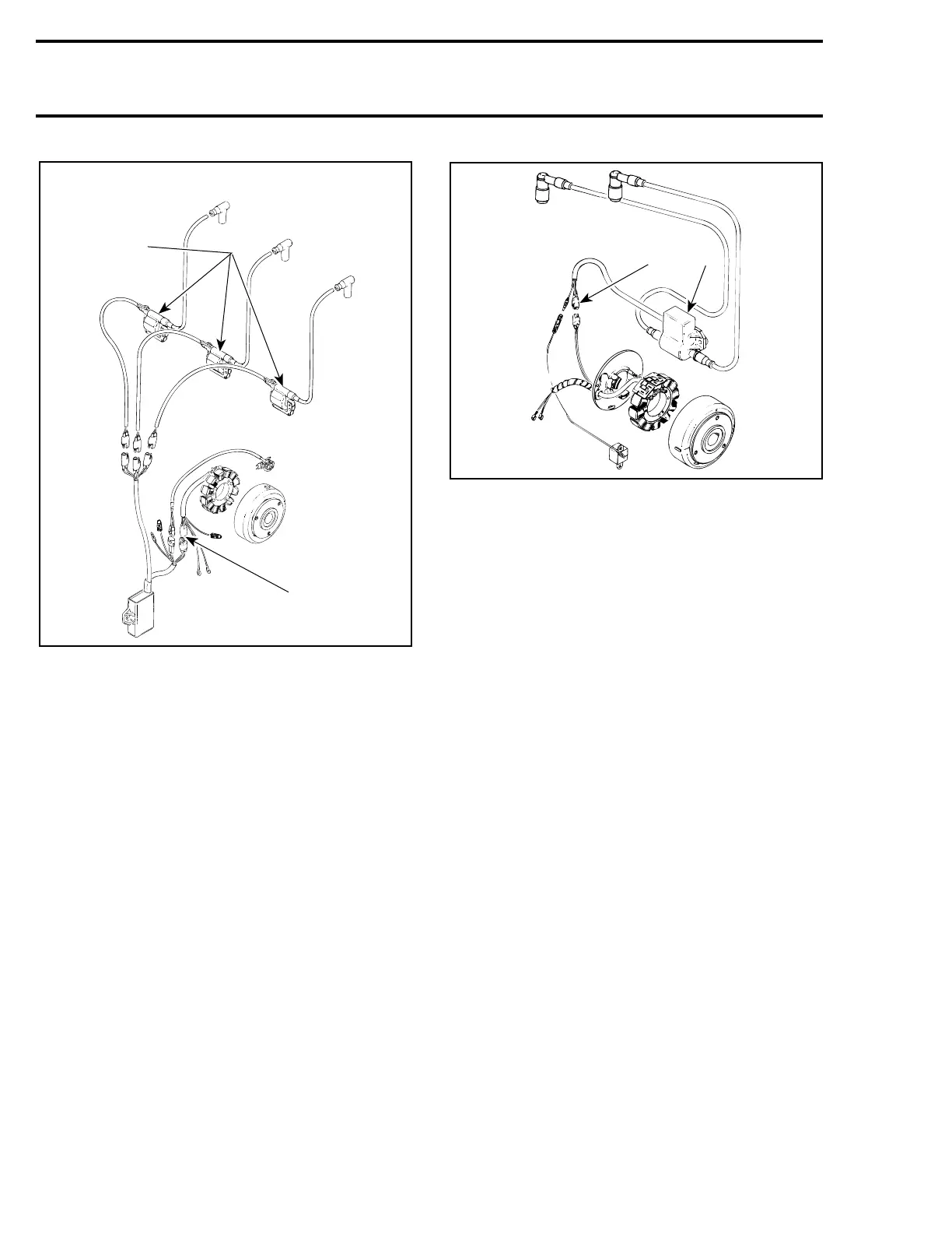
NIPPONDENSO CDI TRIGGER COIL THREE H.T. COILS
1. Separate ignition coils mounted on carburetor flanges
2. Three-wire connector (BLACK / RED, WHITE and RED)
Ducati
The DUCATI CDI system has a combined ignition
module / ignition coil which are mounted on oil
reservoir support.
Ignition module is connected to the ignition gen-
erator coils via a 2-wire connector (GREEN and
WHITE wires).
➂
DUCATI CDI SYSTEM
1. Combined ignition module / ignition coil mounted on air silencer
below carburetor
2. Two-wire connector (GREEN / WHITE wires)
Ignition System Testing Sequence
When dealing with ignition problems, the follow-
ing items should be verified in this order.
Nippondenso
1. Spark occurrence / spark plug condition.
2. Electrical connections.
3. Engine stop / tether cord switches.
4. Ignition coil output.
5. Ignition module output.
6. Magneto output (ignition generator coil).
CAUTION : Whenever replacing a compo-
nent in ignition system, check ignition
timing.
Ducati
1. Spark occurence / spark plug condition.
2. Electrical connections.
3. Engine stop / tether crod switches.
4. Trigger coil output.
5. Magneto output (ignition generator coil).
6. Ignition coil output.
7. Ignition module.
All Systems
The first 2 items can be checked with known au-
tomotive equipment and other items as follows.
1
A06E0ZA
2
A17E0TA
1
2
 Loading...
