Section 07 REAR SUSPENSION
Sub-Section 04 (DRIVE AXLE)
07-04-5
Skandic WT
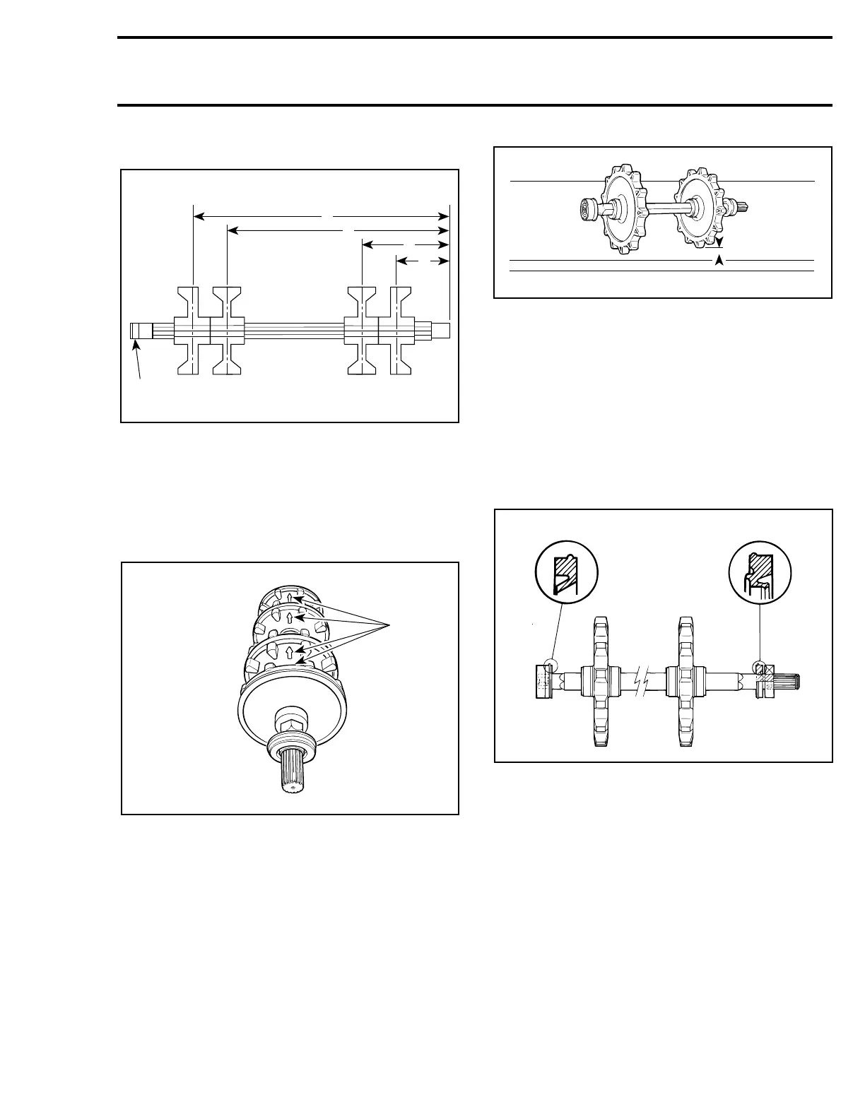
1. Gearbox side
A. 95.5 mm (3-49/64 in)
B. 159 mm (6-17/64 in)
C. 401 mm (15-25/32 in)
D. 464.5 mm (18-9/32 in)
All Models
Ensure to align indexing marks of each sprocket
when assembling.
TYPICAL
1. Indexing marks aligned
The maximum desynchronization for the sprock-
ets is 1.5 mm (1/16 in).
To check this tolerance, place axle assembly on a
plane surface and measure the gap between
sprocket tooth and surface.
1. Plane surface
A. 1.5 mm (1/16 in) MAXIMUM
CAUTION : The same sprocket must not
be pressed twice on the axle. If synchroni-
zation is found to be defective, use a new
sprocket.
6,8, Drive Axle and Seal
When assembling drive axle, always position a
new seal on each end of drive axle (if applicable).
Locate seal lip as illustrated.
1. Grease seal type
2. Oil seal type
11, Bearing Protector
At assembly, flat side of bearing protector must
be against bearing.
A22D18A
B
C
D
1
A
A24D05A
1
 Loading...
