Section 04 ENGINE
Sub-Section 02 (454, 583 AND 670 ENGINE TYPES)
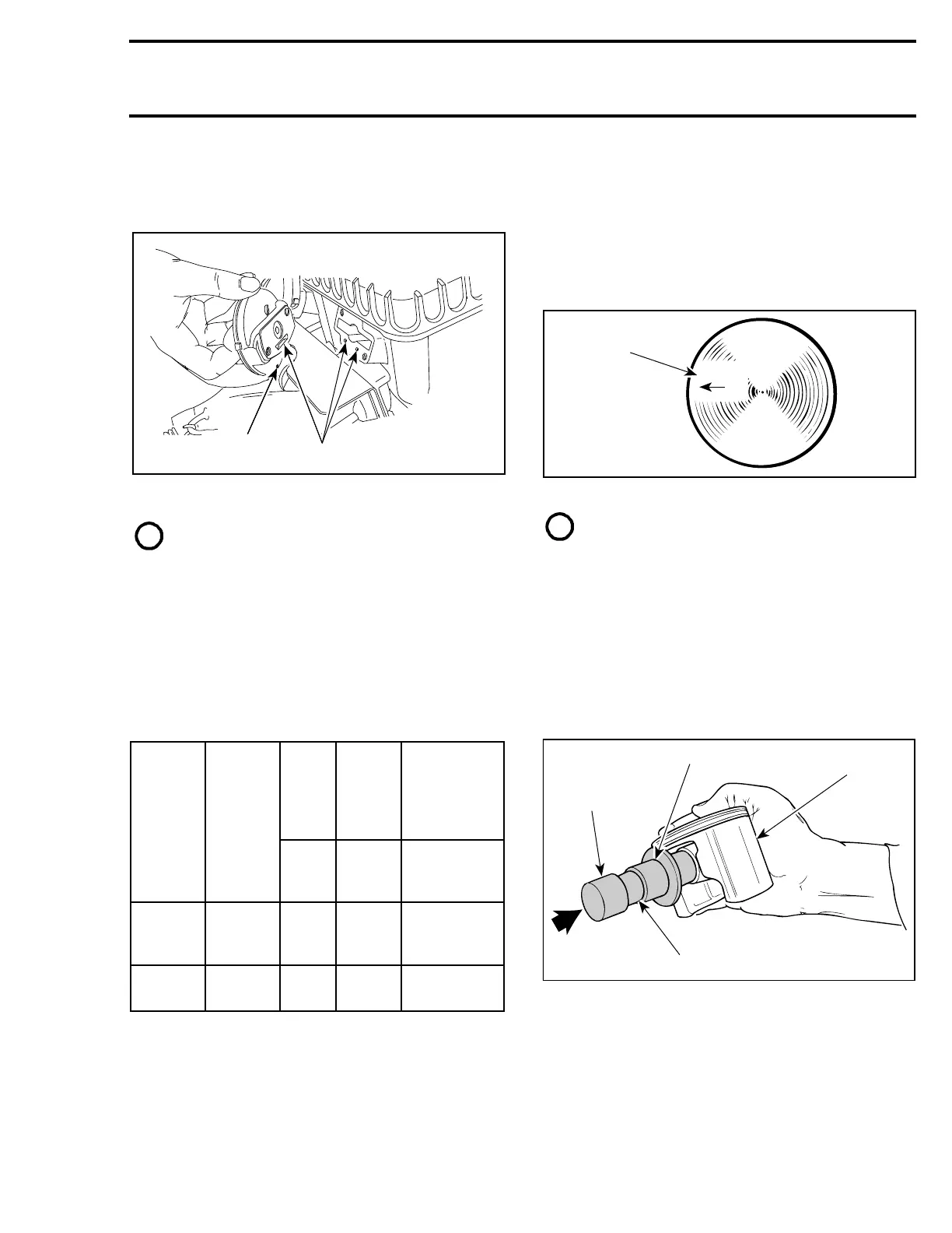
04-02-5
RAVE System
Check valve rod housing and cylinder for clogged
passages.
1. Draining hole
2. Passages
NOTE : Oil dripping from draining hole indi-
cates a loosen clamp or damaged bellows.
4, Valve Rod
Check valve rod for straightness.
10, Bellows
Check for cracked, dried or perforated bellows.
13, Spring
Make sure both springs installed on the engine
have same characteristics.
ASSEMBLY
22,23,24, Piston Pin, Circlip and Piston
At assembly, place the pistons over the connect-
ing rods with the letters “AUS” (over an arrow on
the piston dome) facing in direction of the exhaust
port.
1. Exhaust
NOTE : Spare parts pistons and cylinders
are identified with a green or red dot, it is
important to match the piston with the cylinder of
the same color.
Use piston pin puller (P / N 529 0210 00) to ease
piston pin installation.
To minimize the effect of acceleration forces on
circlip, install each circlip so the circlip break is at
6 o’clock as illustrated. Use piston circlip installer
(P / N 529 0169 00) for all engines except 670 and
(P / N 290 8770 16) for 670 engine.
1. Place circlip in
2. Restrain
3. Oil
ENGINE
TYPE
SPRING
P / N
WIRE
DIA.
FREE
LENGT
H
PRELOAD IN
N (LBF) AT
COM-
PRESSED
LENGTH
mm
(in)
mm
(in)
OF
14.7 mm
(.579 in)
454
420
2399 45
1.0
(.039)
48.5
(1-29/
32)
20.3
(4.55)
583 and
670
420
2399 48
1.0
(.039)
38.0
(1-1/2)
19.3
(4.34)
1
2
A24C05A
 Loading...
