Section 04 ENGINE
Sub-Section 01 (503 ENGINE TYPE)
04-01-4
NOTE : The following procedures can be
done without removing the engine from
chassis.
CLEANING
Discard all gaskets. Use Gasket Remover (P / N
413 7085 00) to clean mating surfaces.
Clean all metal components in a non-ferrous met-
al cleaner.
Scrape off carbon formation from cylinder ex-
haust port, cylinder head and piston dome using a
wooden spatula.
NOTE : The letters “AUS” and arrow on the
piston dome must be visible after cleaning.
Clean the piston ring grooves with a groove clean-
er tool, or with a piece of broken ring.
DISASSEMBLY
15,16,17, Piston, Piston Pin and Circlip
Place a clean cloth over crankcase to prevent cir-
clips from falling into crankcase. Then with a
pointed tool inserted in piston notch, remove cir-
clip from piston.
To remove piston pin, use piston pin puller (P / N
529 0210 00) as follows :
– Fully screw puller handle.
– Insert puller end into piston pin.
– Screw (LH threads) extracting nut.
– Hold puller firmly and rotate puller handle coun-
terclockwise to pull piston pin.
NOTE : The PTO cylinder or fan housing
have to be removed to give access to MAG
piston pin with the puller.
NOTE : 0.25 and 0.5 mm oversized piston
and rings are available if necessary.
INSPECTION
Refer to ENGINE DIMENSIONS MEASUREMENT
04-04.
ASSEMBLY
15,17, Piston and Circlip
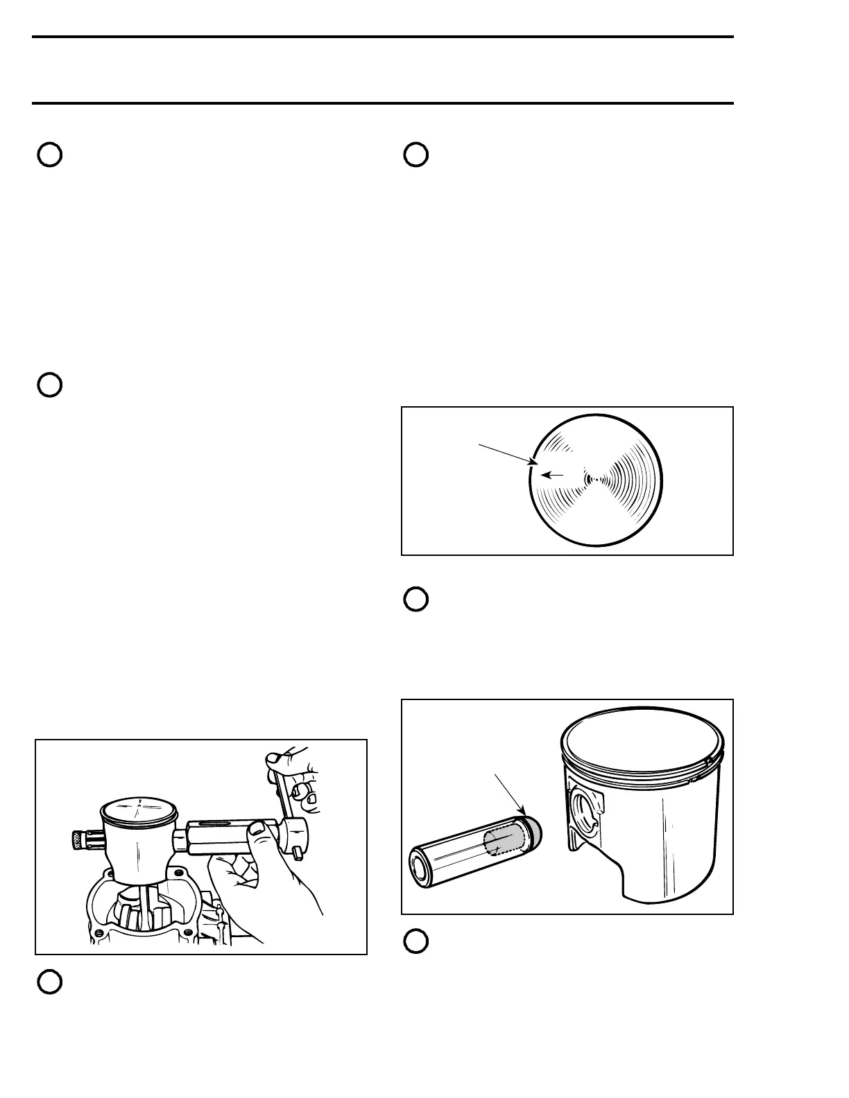
At assembly, place the pistons over the connect-
ing rods with the letters “AUS” (over an arrow on
the piston dome) facing in the direction of the ex-
haust port.
1. Exhaust
NOTE : Spare parts pistons and cylinders
are identified with a green or red dot, it is
important to match the piston with the cylinder of
the same color.
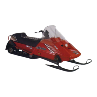
To center the piston pin with the connecting rod
bearing, use centering tool (P / N 529 0091 00)
NOTE : The circlip on the opposite side can
be installed before pin installation, the tool
will easily go out.
A01C01A
AUS
1
A01B1SA
529 0091 00
 Loading...