EasyManua.ls Logo

Skipper EMES60 - 5 Technical Details; Circuit Board Layouts

Skipper EMES60
63 pages
Print Icon
To Next Page IconTo Next Page
To Previous Page IconTo Previous Page
Loading...
39
5 Technical Details
5.1 Circuit board layouts
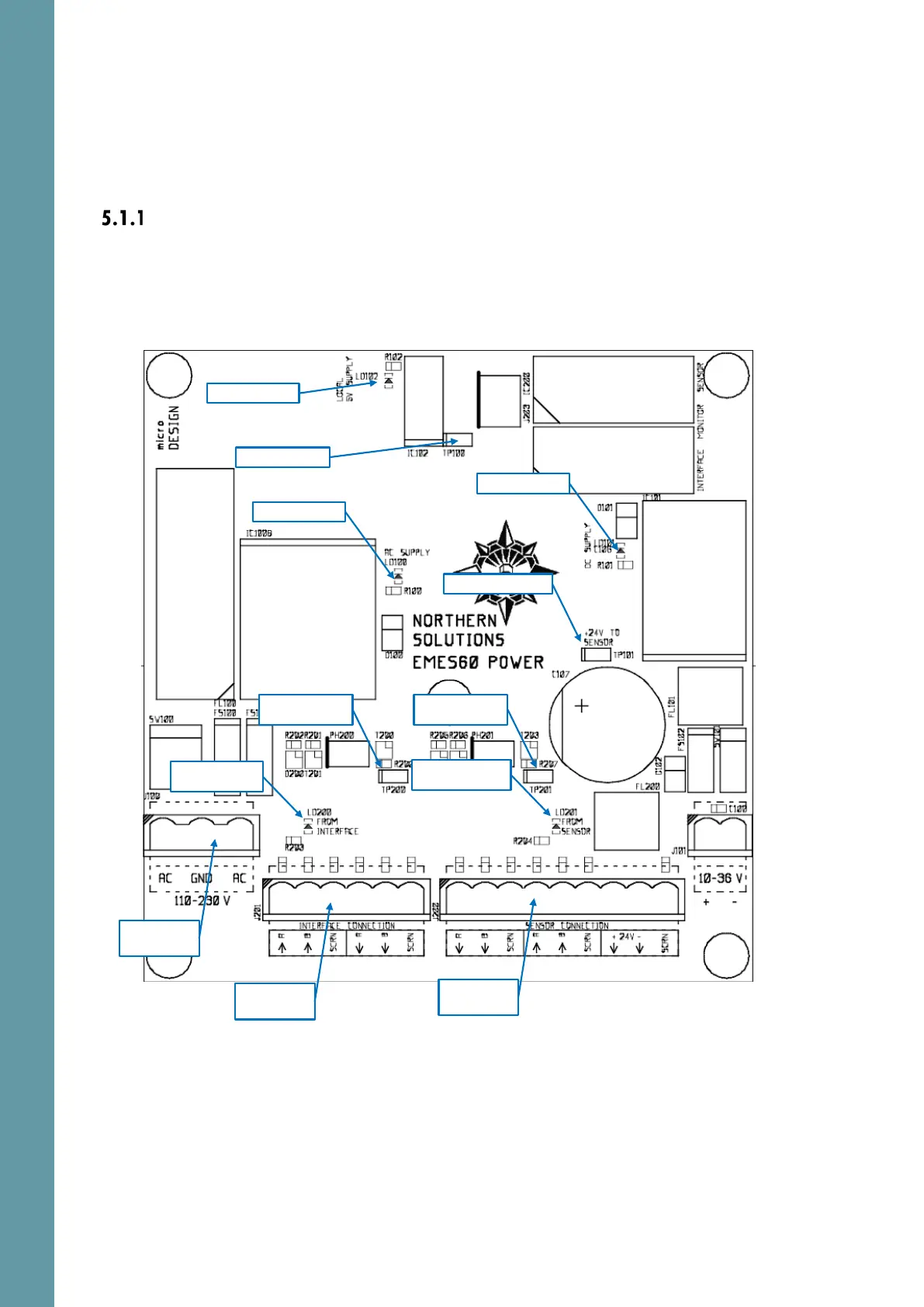
Power Board Layout
The Interface Unit contains two Power Boards, one for the echosounder and one
for the speed log.
The locations of connectors, LED lights and test points are shown below. Pin 1 on
the connectors is indicated by a mark in the corner of the connector drawing.
Mains Power
connections
Connection to
Sensor
Connection to
Interface Unit
Test point: Local 5V
Red LED: 24V from AC
Red LED: 24V from DC
Green LED: Local 5V
Red LED: NMEA0183
from Interface
Green LED: NMEA0183
from Sensor
Test point: 24V to Sensor
Test point: NMEA0183
from Interface
Test point: NMEA0183
from Interface

Other manuals for Skipper EMES60