Adjusting the ready position
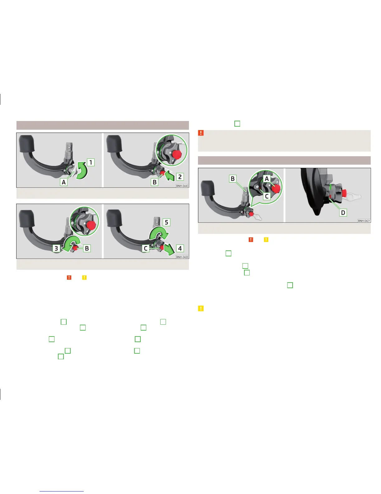
Fig. 112 Remove cap from the lock / insert key into the lock
Fig. 113 Setting the ready position
Read and observe and on page 120 first.
The tow bar must be set prior to installation to the standby posi-
tion » page 121, A correctly set ready position.
If this is not in the ready position, then this must be set to the standby posi-
tion as follows.
›
Grip the tow bar below the protective cap.
›
Remove the cover
A
from the lock in the direction of the arrow
1
» Fig. 112.
›
Insert the key into the lock
B
in the direction of arrow
2,
so that the arrow
on the key symbol
shows.
›
Turn the key
B
to the stop in the direction of arrow
3,
so that the arrow on
the key symbol
» Fig. 113 shows.
›
Pull the hand wheel
C
in the direction of the arrow
4
and turn in the direc-
tion of the arrow
5
to the stop.
The hand wheel
C
remains locked in this position.
WARNING
If the tow bar cannot be correctly placed in the ready position, then it must
not be used.
A correctly set ready position
Fig. 114 Ready position
Read and observe
and on page 120 first.
Correctly adjusted standby position » Fig. 114
The key
A
is in the unlocked position - the arrow on the key points to the
symbol
.
The locking ball
B
can be pushed fully into the tow bar.
The red marking
C
on the hand wheel points to the white marking on the
ball bar.
There is a clear gap of approx. 4 mm
D
between the hand wheel and the
tow bar.
The ball bar is thus set ready for installation.
CAUTION
When in the ready position, the key cannot be removed from the lock.
121
Hitch and trailer

 Loading...