PRECAUTIONS
Please read all the instructions before proceeding with installation. NOTE: Not all parts included with fan may be
necessary for installation.
CAUTION: A qualied electrician should complete all wiring. Install following all local codes and in compliance with the
National Electric Code ANSI/AFPA NO. 70 or CSA C22.1 for all of North America.
Skytech FK-165-ESC
REV 4-10-12 Page 2 of 5
Mounting Bracket
Bend Tab
Air Deector
!
Air Deector
Mounting Bracket
Foam Strips
!
Fig. 1
Fig. 2
INSTALLATION
NOTE: Novus appliances do not require the use of the air deector.
WARNING: Turn electrical power OFF at the circuit breaker before beginning this installation.
1. Unplug the old fan system (if applicable) and remove it from the appliance. In some cases the existing mounting
bracket may be used. If not use the mounting bracket supplied with this fan kit.
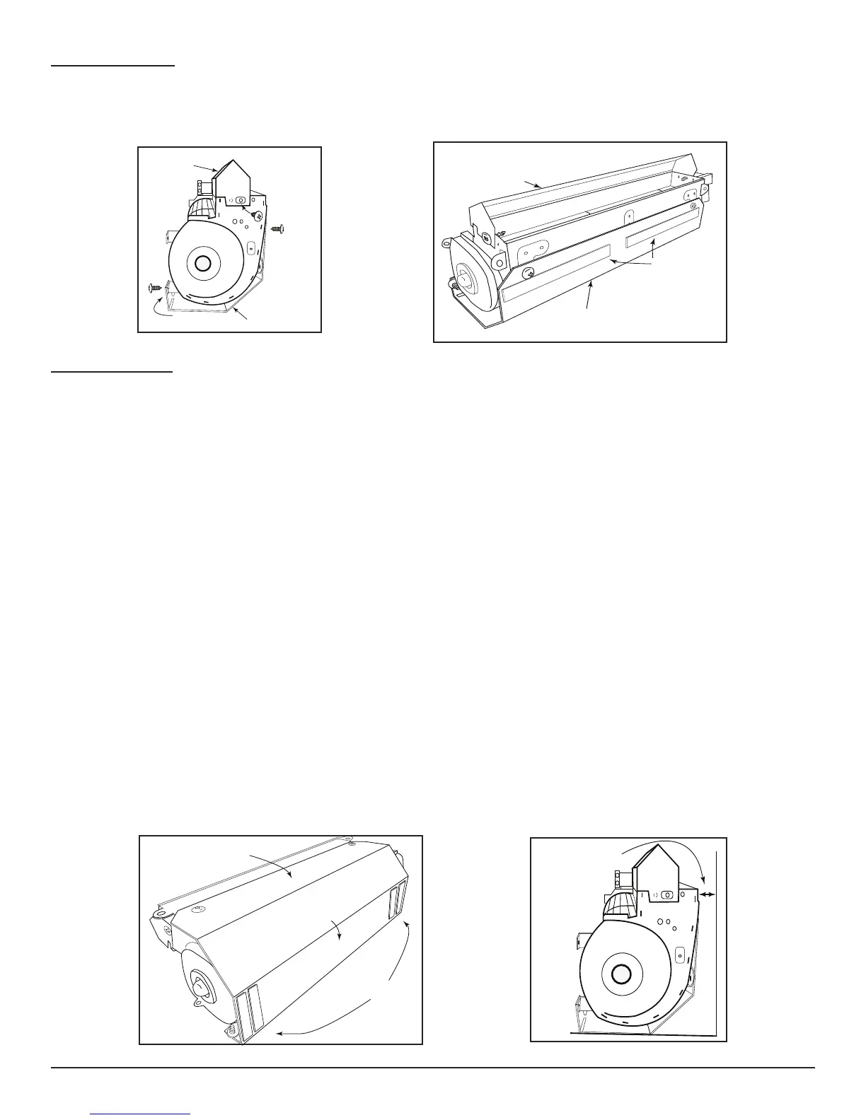
2. Mount the air deector on the F-165-1 fan. See Figure #1. The deector sits on top of the fan as shown and
secures to the middle hole of the fan on each side. Note: Some installations may not require air deector.
3. If using the mounting bracket supplied with the FK-165-1 bend the tabs as shown in Figure #1. Note: In some
installations you may use the existing mounting bracket from the appliance. Secure the mounting bracket for the
fan in four places using the supplied sheet metal screws mating to the aligned holes on the fan housing.
4. Peel the protective covering from the foam strips and place them to the mounting bracket as shown in Figure #2.
5. Cut the magnets in half using tin snips as shown on front page (part #5). Peel the protective coating from the
magnets place them on the bottom of the
mounting bracket as shown in gure #3. OPTION: You can use
two of the magnets to secure the FK-ESC to the base of the appliance.
6. Attach the FK-ESC wires to the F-165-1 fan as shown in the wiring diagram (Fig.5).
7. Install the new F-165-1 fan housing in the rear of the appliance where the previous fan was installed.
8. Pull the fan housing slightly away from the back metal wall (1/8’’ to 1/4’’) of the appliance. The magnetic feet will
hold the housing in place. (See Figure #1)
9. Attach the F-165-1 fan ground (green) wire to an accessible ground source.
10. Plug the FK-ESC into an approved electrical junction box and lay inside appliance accessible for operation.
11. If installing this kit into an appliance with a Millivolt valve system use Figure #5. If installing this kit into an IPI
electronic system use Figure #6.
Mounting Bracket
Bottom of Mounting
Bracket
Magnetic Strips
Fig. 3
1/8” - 1/4” Spacing
From Back Wall
Fig. 4
Toll-Free 1-866-667-8454
NorthlineExpress.com
www.NorthlineExpress.com
Toll-Free 1-866-667-8454
NorthlineExpress.com
www.NorthlineExpress.com
 Loading...